Collective Wisdom – The DN Iceboat
Seven Years of Internet Archives
1998-2004
Edited and Arranged for Easy Reference
PLUS
Selected Reprints from Runner Tracks
Ken
Smith
Editor
Contents
Click on a page number to go to that page. (Control – Click in WORD) Use your Back arrow in the top menu to return to this table.
What is a DN?
408
Posted by: Paul Goodwin on October 07, 1999 at 08:27:51:
In Reply to: Pardon my ignorance, what's a DN? posted by Dennis Collins on October 06, 1999 at 12:28:54:
![]()
A DN is a small one design iceboat. It is a single seater
roughly 12ft long and 8ft wide. By far the most popular
iceboat in the world, with around 150-200 boats participating
in the World Championships each year.
You can get more info, some pictures, and links to other site here:
IDNIYRA website www.idniyra.org
583
Posted by: A. Brown on December 01, 2001 at 14:07:08:
Perhaps there could be another forum here for those of us that do not race, but are enthusiastic recreational iceboaters. It would be nice to have a forum for options that are not necessarily race legal.
With a little bit more flexibility, you might even see your membership improve.
586
Posted by: Ken Smith on December 02, 2001 at 00:51:58:
In Reply to: Perhaps.... posted by A. Brown on December 01, 2001 at 14:07:08:
A. Brown:
There are many items and discussions about not-class legal things on this board, and it is the most active board on ICE I've seen. If you enjoy sailing, can you deny that you've seen if you are faster than the others on your lake? If so, you are racing. After investing the time and effort to build something close to a DN, the little differences should be understood so that when you are done you have a boat which IS or can be made into a DN, so you can race with the best as well as the locals. Everyone loves to see entheuastic sailors, because if they are good and travel to sail, soon they will be racing.
Whenever someone asks about something which is not "DN class legal" you can bet a reply will point this out. This is neither criticism nor judgement about the proposal, just information. Take it or leave it. I built a hull with some carbon fiber reinforcement once, and decided to race. I had to deal with the carbon to participate. If I had known, I would have used something else.
Build what you want. But if your DN is not class legal, you will not be able to participate in a big race.
Besides, it is hard to improve on these simple, elegant, highly portable little boats. You can cut some costs with sails and the like, but they can easily be upgraded. Making the boat longer, wider deeper or round will almost certainly make it harder to load on a vehicle, heavier, harder to sail, or unable to sail in conditions adequate for a DN. They are already well evolved.
Ken Smith
DN4137
589
Posted by: mark kiefer on December 02, 2001 at 19:47:43:
In Reply to: Perhaps.... posted by A. Brown on December 01, 2001 at 14:07:08:
My friend Al sails out of central Minnesota on a "gambit", sorry Lloyd, that he has maybe 60 total dollars in. In terms of fun per dollar, it's hard to beat his ride. You can build a sail out of tyvek house wrap for about 12 bucks, he built his out of "free" 1.5 oz nylon, and goes 35-40, or in the alternative you can spend two weeks (if you can sew 6 oz, most machines won't suffer that job silently), the 170 bucks and still go 35 - 40, on clear ice if it's blowin, read ZERO GAIN over house wrap.
As for me, I like going as fast as I can in a DN, if I want to go any faster, I'll use the car.
The primary purpose of this forum is to engage a dialog where faster, more experienced sailors give their experiences to enable sailors (choppers like us) to sail faster and safer. Fast is fun, faster is funner.
If you get advice from the best in the world, (and some of that was posted on this thread earlier, by "Jane") and don't like the advice, don't blame the messenger.
It' real simple, any dn (flavor) iceboater can get a brand new sail with battens for 600 clams and a great used one for a third of that, they last recreationally forever(literally), and run laps around almost any other sail run up a similar mast. If you think you can save money or time, or get better performance by doing it yourself, you're nutz, go buy a couple yards of tyvek, and do a "but the wind is free", on the cheap program, we'll understand.
think ice
4695
History and sources
498
Posted by: Paul Goodwin on August 02, 2000 at 06:56:26:
In Reply to: Plans wanted posted by Doug Stearns on July 27, 2000 at 17:31:08:
The obvious place to look for the Gougeon plans is to place
a call to the Gougeon Brothers, Inc. I think they have quit
selling their plans, but I could be mistaken. [Not available in 2004]
The current plans available from the IDNIYRA are very similar
to the Gougeon plans, and take many of the construction ideas
directly from the Gougeons. I believe the IDNIYRA plans are
more versatile, especially in terms of their suitability to
a wide range of sailors.
If you do get a set of Gougeon plans, definitely move the
#4 bulkhead (front of cockpit) forward to make the cockpit
maximum length. This will allow a taller sailor to get
down in the cockpit to reduce wind resistance.
As an alternative (or in addition) to scale plans, I offer
a set of full-size templates for the hull. This can save
a lot of time and effort by eliminating the lofting stage
(converting from scale to full size measurements). Feel
free to email if you need more info.
549
Posted by: Paul Goodwin on February 09, 2001 at 07:49:27:
In Reply to: Re: Plans wanted posted by Tim Heine on February 05, 2001 at 19:15:41:
Plans for the DN iceboat are available from the IDNYRA Treasurer for $15. To get a set, print the membership application form from the IDNIYRA NA website and check the section on plans. Send the form and a check to the Treasurer (address is on the form).
While your at it, why not join the IDNIYRA???
Here is a direct link to the membership application form: [corrected 2004]
- IDNIYRA membership form: http://www.sailingsource.com/ice/member.htm
- OR through the website: www.IDNIYRA.org
811
Posted by: BILL GRENIER on October 21, 2003 at 18:07:30:
In Reply to: Re: Plans wanted posted by Paul Goodwin on August 02, 2000 at 06:56:26:
I got some plans from you a few years ago, but was a little intimidated by the hardware involved in making a DN ice boat, I already have a aluminum mast and sail from an old sailboat which I hope to use, Is there anyone who supplies the hardware for the boat? I would like to finally get started.
812
Posted by: Geoff Sobering on October 22, 2003 at 10:15:49:
In Reply to: Re. hardware posted by BILL GRENIER on October 21, 2003 at 18:07:30:
Sarns Hardware (http://www.sarnshardware.com/) is the tradidion supplier of DN hardware (basically the designs shown in the official plans). Steve Duhamel (Northwind Iceboats) at 781-826-8004 has a nice collection of European parts; he is a frequent poster on the Yahoo! Iceboating group (http://groups.yahoo.com/group/IceBoating/).
There are any number of other suppliers (some listed at the top of the Bulletin Board). Also, the "Vendors" section of the Iceboat.org page may be helpful (http://iceboat.org/cool_links.htm).
Good luck with your boat!
Cheers,
Geoff S.
P.S. You may want to reconsider the use of a soft-water mast/sail combination. It will probably work, but it will likely be 1) way too big, and 2) way too full. The DN is considered a fairly overpowered iceboat (for it's size); it has a sail of about 70 sq ft. For comparison, a Laser softwater boat has a 75 sq ft sail.
Buying
Used boats and repairs
396
Posted by: Ken Smith on July 27, 1999 at 07:27:03:
In Reply to: Restoring an old DN iceboat. NEED HELP!!! posted by Oliver Rush (sail # 3339) on June 19, 1999 at 19:47:36:
Sources for material:
http://www.paw.com/sail/ice/
Click the suplier list for dealers and other information.
The following is a checklist to get an old boat on the ice. It may or may not be complete.
Rigging: No sign of rust or cracks on fittings especially near holes. Clean rust, replace if cracked. Wire not kinked or frayed. Halyard works. Pins and shackles in good shape, especially those on the fore stay! Blocks turn freely. Ratchet block works. The forestay is the most stressed rigging on the boat. If in doubt, replace it with hardware from most any rigging shop. Length affects mast rake.
Steering: NO SLOP. If slop is present in through-hull bearings, replace bushings. They can be made or bought. If slop is from wear or corrosion on on vertical chock tube or steering head tube, replace. If slop is from push rod, either replace rod ends (new rods)by purchase form a supplier like McMaster-Carr or a parts supplier, or replace rod or pins (old style slotted bar stock). If slop in steering head, try tightening, or use tapered pin or bolt rather than spring pin, a machine shop can fix. Or replace the piece.
Hull: No cracked joints-fix with epoxy, fill cracks. Plank clip or plates tight. Mast base screws tight. Connection of blocks to deck tight. If any screws are loose, use sroong filler in epoxy to fill hole and re-drill. Tighten joints inside cockpit so rain and snow won't get into inner floor.
Plank: If warped, replace. Chocks ALIGN. Bolts tight and none stripped. If stripped, tap to next size or replace. See details elsewhere on alignment. Alignment is one of the most important items for speed!
Appearance: Your choice. Minimum requirement is to seal all wood with epoxy or varnish or paint, and especially cockpit floor to exclude moisture.
Structure: Mast step structure and listings between the floors are of most concern. If the floor is soft or you are worried about the mast step, the bottom skin can be removed by routing off the edges and glued areas. Inspect or repair and reskin with a good qality 1/8 inch mahogony, poplar or other light ply.
Mast: Sail track is clean, halyard works, bearing at base is strongly attached, hound is secure and not cracked at stay connection.
Boom: no splinters, blocks work. Generally straight.
Sails runners are obviously necessary, and are the speed locker. The more work and higher quality these components are, the faster you sail. Old and mangy still are fun for fun sailing.
Ken
Thinking about building
Hull Kits
[The bad news is that
no one is packaging a kit as far as I know in 2004]
588
Posted by: Jeff Soderholm on December 02, 2001 at 08:54:36:
In Reply to: Thanks for your reply posted by Mike D. on December 02, 2001 at 07:11:09:
Mike I think the plans most use now are the wedge style or Gougoun plans
which varying greatly from the original Sarns plans. I am not sure if those are
wedge style plans that you have but I would make sure that they are if you are
going to go through all the effort. I like the idea of the full size Goodwin
plans as you can lay everything out right on the plans. I am sure Ken can
provide better input on plans. Regarding kits Steve at Northwind Iceboats in
Massachusetts has made kits in the past. He preforms the side panels and you
glue the pieces up etc.. If you are interested in finding out more you can
e-mail him at nth1@aol.com there is a list of prices of other equipment at the
NEIYA unclassifieds site at
http://www.concentric.net/~dn4762/events/postings.shtml
good luck and Think Ice!
Jeff
585
Posted by: Ken Smith on December 02, 2001 at 00:34:04:
In Reply to: DN Kits posted by Mike D. on December 01, 2001 at 18:23:28:
Mike:
No one is selling wood kits that I know of. Several of the shops selling hulls will sell partially finished boats so you pay labor instead of bucks.
Paul Goodwin sells plans and instructions as discussed elsewhere in the bulletin board. Try clicking on major headings, and brouse the messages. Raw materials are a short, though expensive list.
The major components are usually quarter sawn sitka spruce for the side boards, two pieces 13 feet long, 5/8 thick, seven inches wide. Narrower widths mean you may need to edge glue some to make the deeper portions of the sideboards, which is not a big deal. If you get 15 or 16 feet, the rest of the parts of the boat can come from that and the scrap. You also need 1/8 inch plywood. Light weight okume or mahogany or poplar is adequate. Birch is overkill. If any is making doors at a factory near you, door skins have been used in many boats. You will need three or four sheets for all the decks. You are covering the top and bottom so the 12 foot by 30 inch hull, but much is narrow. You will need a few small thicker pieces of wood, but lumberyard or scrap can work. You will need a gallon of good epoxy.
Your plank will need enough wood to make eight feet by seven inches by 1-1/4 inches in three layers.
All the hardware can be bought from Sarns.
Add boom, sail, rigging, and runners and you are off!
Let the DNboard know where in the world you are. Others will likely help.
Good Luck!
Ken Smith
DN4137
587
Posted by: Mike D. on December 02, 2001 at 07:11:09:
In Reply to: Re: DN Kits posted by Ken Smith on December 02, 2001 at 00:34:04:
Ken, thanks for your help.
I have a dated set of prints (dated Oct, 1991). This design doesn't have the concave bottom like what P. Goodwin has on his website. So I guess at this point I have 3 questions:
1. Is the concave bottom design worth doing vs. my dated prints?
2. You mention a 13 foot length for the sides. The list on this set of prints
says 12 feet. Will 12 feet do it, or is 13 what I really want?
3. Lastly, the materials list calls for one 4x8 ply sheet for the decks and
sole. This must mean there is a joint on the underside of the 12 foot fuselage.
I haven't seen it called out on my prints, though. What station line is that
joint at?
Again, thank you for your help.
Mike.
ps. I am located on the geographic southern fringe of iceboating, in Lincoln, Nebraska. Some seasons we have 3 full months of ice, like last year. Other years, we're lucky to get 6 weeks straight with safe ice.
590
Posted by: Ken Smith on December 03, 2001 at 00:49:47:
In Reply to: Thanks for your reply posted by Mike D. on December 02, 2001 at 07:11:09:
Mike:
To answer your questions:
1. Is the concave bottom design worth doing vs. my dated prints?
It is a preference thing. The boats look cool and provide a touch more ground clearance. They appear to me to be a tad harder to build, but I have not built one of them. Your plans will make an adequate - excellent boat. You will have a few lofting tricks to learn. I have two boats built to plans of the same vintage and Jan Gougeon is using the boat (modified, lengthened and repaired) that was used to make the 1988 vintage Gougeon plans. It will work fine. Most boats bring the stern up as far as the plans allow to keep from dragging the tail around, but this is not hard and if not done, is not critical.
You did not say whose plans you have. Norton and Gougeon would sell plans then. Both boats are sturdy and adequate. The plans in the yearbook make a good boat as well. Make the square pieces in the corners triangles, and these are Gougeon plans, almost.
Two mods are highly recommended: Make the boat a tad less than maximum length (12 feet) with maximum overhang at the bow. The Gougeon plans go toward minimum length for weight, but this is one of Jan's mods to his original boat to make it longer. Second, make the cockpit nearly maximum length. Read the board elsewhere to see why.
2. You mention a 13 foot length for the sides. The list on this set of prints says 12 feet. Will 12 feet do it, or is 13 what I really want?
12 feet will make a boat of near minimum total length. With the bend in the side, the hull length will be less than the plank length. This is okay, but the longer hull gives you a little more leverage to pull in the sail as the blocks are further aft. You need three bulkheads in the boat plus some a piece under the mast. This can come from your sideboard planks if there are no large scraps around your area. If you are goint to find a sitka plank to make the side boards, get two long enough for these pieces too.
3. Lastly, the materials list calls for one 4x8 ply sheet for the decks and sole. This must mean there is a joint on the underside of the 12 foot fuselage. I haven't seen it called out on my prints, though. What station line is that joint at?
Your choice. A five to one scarf joint is more than strong enough to deal with loads carried by the lower skin. The most highly stressed skin portion is between the bow and the dolphin striker under the mast. The joint will be behind than in any case. But most 1/8 (3 mm) plywood comes in smaller sheets than 4 x 8. Do NOT use cheap mahogany ply with white middle layer. It is strong enough, probably, but is splintery, poorly glued and hard to work.
A few other notes. There are two or three methods to build. This is what I used. Others build the sideboards and all the listings then add all the skins. Both work, its a preference thing.
A. The sideboard plank width should match the side board profile you want, deepest depth. You can edge glue some pieces from the trimmed off bow or stern to get the depth if it exceeds the material you found.
B. I do not remember where I read about building a DN before my first project, but it may have been in Think Ice. I had visited Tom Hammel, Joe Norton, and two other projects in progress, so I had a good picture of what others were doing.
C. I scarfed together the bottom skin, laid it out on a ladder-bench I built. The bench was built from two 2 x 6 x 12's with 1 x 3 cross members. If you make the table curved like the Goodwin profile, you get that bottom contour.
D. I laid out the boat on the bottom skin and glued the listings, longitudinal pieces, back-up blocks, and under-mast structure right to the bottom skin on top of the pencil lines from the plans.
E. I used a false bulkhead instead of the seat back to get the shape right and I fabricated teh bow and stern blocks. These get glued later. The side boards can be sawn and reglued on a fixture to get the curve, but I just glued them to the bow block one night, and bent them around my bottom structure and bulkheads and glued them to the stern block right on the table. I lifted them off to plane a nice square bottom surface and took off material to curve up the stern 1/2 inch or so, from the plank position aft. Then I glued the side boards and end blocks to the bottom skins and all the other structure.
F. The rear deck listings and structure went in next, as the exact shape could not be predicted by me until the process was at this point. The shape of the seat was the biggest pain, as it is slanted and joins a curves side.
G. Skin the floor, install knees, hand rails and foot brace boards, skin the forward deck, drill the holes for the steering tubes, and mount the hardware.
I built my first boat with a good saber saw, a hand plane, a borrowed table saw, and a borrowed router. Sawing the sideboards for the bend was the scariest cut. I needed help with that and I needed an extra set of hands for the side board bending and gluing. Make all the skins hang over the edge and finish with a laminate blade or a radius blade in the router.
No sweat.
Opti DN for kids
[See www.icesailing.org and go to the youth
link to find plans, pictures and details]
626
Posted by: Doug Gaudet on February 15, 2002 at 10:44:04:
I got these three files from Jan Adsten of Sweden and I thought it might be good
food for thought as to how we get our younger sailors into iceboating, cheaply,
easily and with resources at hand.
Jan also sent me, along with the insert crown diagram, design diagrams for this
DN-Optimist. It is smaller than a DN, very limited technical construction and
uses an Opti's sail and mast. Jan advertises them in Sweden to get 10 - 16 year
old in an iceboat which is inexpensive easy to make, and much more stable in
various wind conditions. Also a good configuration for the "newbie's"
from the softwater world.
I have emailed him for the last several days and he points out that it is not a
DN but also it is not intended to be one. It is intended to get the young
interested and older sailors out for their first iceboat adventure . Because,
as some one pointed out earlier in the discussions last year, regarding
beginners "a sailor who is iceboating for the first time will still find a
"slow" ride on an iceboat FAST. My yacht club maintains about 10
Opti's for the junior sailing program, now whether they would let us use the
rigging remains to be seen.
I have three files from Jan and would email them to anyone interested. They are
not big and they are WORD documents, so they are easily viewed, saved or
printed.
Think about this first
Love this boat
183
Posted by: Paul Goodwin on October 04, 2001 at 15:42:28:
I would have to disagree with the perception that the
current DN is too complex. There is a misconception
that you need to spend a great deal of time (or money)
to campaign a competitive DN. It is true that to win
the World Championship (or NA for that matter) it
helps to have an arsenal of highly tuned runners, the
latest carbon/glass mast, exotic chocks, sail tuned
to fit your particular mast, etc.
But if you look closely at the top sailors, you'll
find that a sailor can be very competitive with a much
more pedestrian setup. A glass (or carbon for those
with a carbon fetish) mast is pretty much a necessity.
Insert runners are also mandatory for top competition.
A plank tuned to each sailors weight is also a given.
The sail must be designed to fit the type of mast
you're using. After that, I believe it's mostly
smoke and mirrors (and perhaps a little sailing
ability -- don't you think???).
The reason the top sailors carry a pick-up truck full
of runners is to have the "ideal" runner for any ice
condition they may run across. If a sailor is willing
to give up the idea of winning on the unusual days
(3/4" of crusty snow, or 2" deep not-quite-frozen
slush), then you can get by with 2 sets of runners
for 90% of conditions. The two sets I use almost all
the time are 36" x 3/16" inserts, and snow runners.
Now, I do have more runners, and use them if the
conditions warrant. 1/4" inserts for heavy wind and
clear ice, angles for slush, and Sarn's plates for
sailing on dirty ice (they are easier to sharpen then
440C inserts). But I could easily get by without them.
While I've never won a World's or NA's, I think I'm at
least "competitive" (please don't burst my bubble
here...) Let's look at some of the "high tech"
components I use:
Mast: I used the same glass mast (from the initial
prototype build with Ron Sherry) for 5(+?) years
(it's now on Debbie's boat and going strong).
I replaced it with another glass mast, and have
had no problems with it. I don't plan on replacing
it this year (sorry Ron). And anyone who knows me
will confirm that I don't "baby" my equipmant!
Sail: I bought a Boston "F01" to use with my first
glass mast, and replaced it last year with a new
one because the old one looked so bad. I don't
know if the new one is any faster, but it sure
looks better. Neither of these sails were "tuned"
to fit my particular mast, they were stock "off
the shelf" sails.
Runners: Last year I used 3/16" inserts whenever
the snow was less than 1-1/2" deep, and sometimes
deeper if it was windy. The rest of the time I
used standard Sarns bullnose runners or snow plates.
There were a couple high-wind days when I used the
1/4" inserts, but it was rare. I put the angles on
a couple of times too, but they're usually more of
a novelty than a necessity.
Hull: I've been using the same hull for seven years.
It's been torn apart a couple times, but I just
glue it back together.
Plank: Four years old. I may replace it this year
with a stiffer one. Some people think it's because
I've been gaining weight, but I won't admit it
until I have to join the "100 kilo club".
Chocks: I use a very sexy set of "Strubleized"
chocks. This is the only thing on my boat I would
consider "high-tech". After going to a bonded
chock setup (no alignment possible), I wanted the
stiffest, straightest chocks possible. These fill
that bill perfectly.
Boom: I broke my 8 year old wooden boom (I sheeted
it in half during a regatta, too much adrenalin
I guess). So, I replaced it with an aluminum boom
last year (Forstmann).
Other than that, all my stuff is standard Sarn's
hardware.
The bottom line is, to win races (or at least come
close), what you REALLY need, is a good set of
basic components, runners which have been highly
tuned, very good sailing (specifically iceboating)
skills, and perfect alignment. The basic components
are easy to come by. The runners are also within
reach. It's the "highly tuned" part of the
runners, and the sailing skills that are difficult.
There is definately a skill to sharpening runners.
You'll probably never get it by trial and error
(error is the key word here). You need to learn
how to sharpen runners from somebody that's already
going fast. I'm willing to show people what I know
about it, but you have to ask me. The sailing
skill, well, what can I say. Practice, practice,
practice. There are sailing skills that you can
get by asking (and listening of course). If you
are having trouble with something specific, ask
me and I'll tell you what I know, even if it's
not much.
Oh, and by "perfect alignment", I don't mean just
runner alignment. The alignment of the plank to
the boat, and alignment of hardware on the hull
are also critical to getting the boat tuned up on
both tacks at the same time.
Hope to see you on the ice, we're in this together!
649
Posted by: John Davenport US4961 on March 12, 2002 at 15:55:38:
In Reply to: Thanks, Paul, good decision. posted by Bruce Lowstuter on March 12, 2002 at 11:26:26:
Hi Bruce,
The beauty of this board is that you can ease back and watch the activity and
if you feel you want to interject your opinion, you can jump right in. Most of
my friends think I have an opinion… I don’t find it surprising at all that mast
defection numbers are not published or readily available. It is something that
is coveted by many. In Ron’s cast, he could make a mast made of pasta go fast.
Many won’t talk about their runners much either. Interestingly, the faster a
person gets, the more likely they are to tell you what they were using and why.
The Gougeons are wonderful to talk to because I always walk away a little
smarter because they make you think. I have been using Jeff’s masts for 3 years
now and I have gotten much faster. Maybe as fast as I will ever get because I
sail with my head up my ### most of the time. I’m sure I would have had the
same jump with Ron’s masts too, but I got to know Jeff when I worked at
Harken... I think the point for me is that I can make everything but 2 parts.
The mast and the sail. I might get faster if I bought a plank too, but I like
making planks. And as far a trickle down is concerned, I haven’t seen an
aluminum or wood mast at a big regatta for a while. Except at out regionals
where we encourage EVERYONE to show-up and join in. The reason I might want
another mast would be that I wanted a different deflection. Just like anything else,
they have evolved. The new masts are faster and lighter for sure. If you want a
softer mast, it is difficult to soften them by sanding, without compromising
the wall thickness. They are pretty thin now days. Although I saw a friend talk
a belt sander to his mast at a regatta this year right in front of the launch
site. I would never do that to a good mast. I would rather sell it and get
another. Frankly, they are not that much money. People say DNs are expensive,
but have you ever counted the SUVs in the parking lots at a regatta? $35,000
over 5 years! As far as Paul is concerned, he won’t buy a new mast until his
falls apart. And why should he, he is fast with what he likes. You should see
his favorite sail. I think it is an old paint tarp. I should know, I see it
from behind enough. My point is just pry the wallet open and buy a mast. Unless
you really over bend it, it will last for a long time, be more fun to sail and
you will go faster. My group has come to the conclusion that time spent on
runners is more meaningful. There is where you can really make strides. Here is
another argument for the expense of DNs. How many of us own a soft water
sailboat AND are members of a yacht club? How about the annual Rum budget? Now
for the important stuff, the “Western Region Spring Regatta” is this weekend
March 16th & 17th (414) 299-9305 Hotline update Wednesday night at 9:00
p.m. We can swap masts there. John Davenport US4961 Western Region Rear
Commodore
648
Posted by: Paul Goodwin on March 12, 2002 at 15:51:56:
In Reply to: Thanks, Paul, good decision. posted by Bruce Lowstuter on March 12, 2002 at 11:26:26:
How does Ron beat me around the course??? Hmmmm.... it
must be the mast. Yeah, that's it, if I can get one of
"those" masts (one of the masts Ron uses of course, not
the ones he sells to other people), then I could beat him
at the next Worlds. OH YEAH baby, now there's a plan!
Actually, I get to sail anything of Ron's I want. Most of
our (local) boats are pretty much interchangable, and we
can take an entire rig and move it from one boat to another
without even adjusting the stays! You can learn a lot by
doing this, and sometimes the knowledge is humbling.
The problem with swapping parts (or whole boats) with Ron
is you find out pretty quickly that he isn't winning by
keeping any secrets up his sleeve (or up his mast for that
matter). What you buy from Ron when you order something
is exactly what he puts on his boat at a regatta, he doesn't
use some "secret" mast that was hand selected. What gets
Ron trophies at DN regattas is the same thing that gets him:
1) 1st place trophies at Renegade Regattas,
2) 1st place trophy at a Northwest Regatta "Free-for-all"
(sailing a borrowed Skeeter).
3) Behind the wheel of the overall winner in the Detroit
to Mackinaw race.
4) etc, etc, etc...
What Ron has is loads of experience and training in making
sailboats go fast, and then pointing them in the right
direction when it counts. Ron is meticulous in setting
up his boat. He checks his runners for nicks after EVERY
race, and takes the time to fix them. He goes out and
checks for wind shifts on the course. He practices starts
and mark roundings. He looks at other boats to see what
makes other sailors go fast. Always watching, always
tuning, always checking and rechecking, and always open
to new ideas.
I'm still learning, and will probably never have the
skill level (or the drive to win) that Ron does. But
I pride myself in doing well with minimal equipment, and
I try to keep the stress level low. I'm proof that you
don't need all the latest trick gadgets to be in the top
ten at the Worlds. You need a basic set of good hardware,
and learn to get the most from what you have.
Ron has been slowly and steadily improving his masts.
The biggest change is weight reduction by using carbon
fiber in place of glass fiber. I think he has taken
something like 4 lb out of the mast by using some carbon.
The carbon mast also has a faster (better?) response
time - it snaps back faster after a gust. The downside
is the carbon mast is more costly, and more fragile than
the glass mast. The other big change is he has developed
several (lower) stiffness levels in the carbon mast.
This has been an advantage for light weight sailors (which
doesn't help me at all).
You make an interesting point about Ron and Jeffs "disservice"
to the class by not divulging the stiffness of their masts.
While it might spur some additional sales, I think the
reality is the only truly interested sailors are the ones
trying to develop their own composites masts. Giving them
all the info to do so would hardly make good business sense.
I'll pass the idea by Ron and see if he bites - but don't hold
your breath waiting for the results...
Helmets
218
Posted by: hugh stephens on January 06, 2002 at 10:04:26:
Are there specific requirements for helmets. I understand that hockey helmets are not permitted. Are there other requirements and where can they be found. I am planning to buy a boeri short cut ski helmet. Thanks.
219
Posted by: WWBL on January 06, 2002 at 11:16:08:
In Reply to: helmets posted by hugh stephens on January 06, 2002 at 10:04:26:
I use my motorcycle helmets but the full face-shield models restrict lateral visiblility, are prone to fogging, and they are heavy. The good news is that they are max protection and are very warm. Snowmobile helmets are lighter and don't fog. Both of these types tend to be fairly bulky and are likely to get caught on the boom, which could be dangerous in a tight spot.
I saw the Boeri ski helmets and they are fine but do not have the optional chin guard the Jofa helmet offers. I called on the helmet sale ad in the latest Runner Tracks (1-800-307-7439) and they only have blue large Jofas left but the price is right at $50. Jofas are only 20 oz. but adequate protection. They have several levels of quality.
You will be fine with the Boeri (ski shops say they are better than Jofas but almost all iceboaters wear Jofas), a face mask like for snowmobiling, and a pair of good ski goggles.
Will 5133
243
Posted by: Roger Duffy on March 03, 2002 at 12:02:24:
In Reply to: Re: helmets posted by WWBL on January 06, 2002 at 11:16:08:
I use my hockey helmet which has an Itech full face shield attached. This is a clear plastic shield with vent holes to prevent fogging. If the weather is very cold, I cover the vent holes with saran wrap. If I start to fog up, I poke my finger through the saran wrap, thereby recreating the vents, trying to keep them to the minimum needed for fog prevention and yet still provide wind protection.
Down forces
391
Posted by: Jay McIntyre on January 07, 2004 at 18:43:38:
can anyone tell me how to figure how much downforce a sail produces on the
mast base, I'm running a 18' mast with about 55 sq ft sail.
any help will be appreciated
Thanks
Jay
393
Posted by: Ken Smith on January 07, 2004 at 22:39:05:
In Reply to: down force created by sail. posted by Jay McIntyre on January 07, 2004 at 18:43:38:
** CAUTION ** Incomprehensible engineering gibberish and the need to do math follows! **
Jay:
You have not provided enough information to answer. It is a fairly complex problem, but this may provide enough information to allow you to estimate.
Firstly - Consider the whole boat. The boat will not be tipping over, so the total sail force acting sideways at the center of effort times that height (upsetting moment) will equal the weight-boat plus skipper- acting at the center of gravity times the distance to a line from the from the front to a one side runner (righting moment). The sail center of effort is about one third back from the mast leading edge and between a third and .45 up from the boom, depending on roach of the sail. These two products can be considered equal (upsetting moment and righting moment).
Secondly - Consider the mast. The windward shroud and the forestay act at the hound attachment point at some angle (both horizontal and vertical) to hold the mast up. The upsetting moment of the sail must also be equal to the moment of the shrouds acting on the mast about the base. This is a vector solution and involves some trigonometry, which will not be explained here. But the total force of the shrouds acting parallel to the ground times the distance from the base to the hound is the "mast moment" and it is equal to the other two moments above. Using some math, solve for the tension in each wire (fore stay and shroud). Note that sheet tension can be ignored for now, because its direction of action does not act to balance the sail force sideways. By now you have Tfs (tension in the forestay due to the sail) and Tss (tension in the side stay due to the sail).
Thirdly consider the main sheet. All the force in the main sheet is balanced by tension in the forestay. A new balance of moments, this time main sheet tension times the number of parts at the end of the boom times the distance from the mast base to where the main acts on the boom is the "sheet moment". It is balanced by the product of a new hunk of tension in the forestay acting forward on the mast times the distance from the base to the hound. Since you know how hard you can pull on the sheet, solve for this new bit of forestay tension called Tfm (Tension in forestay due to mainsheet)
Now start adding forces. The part of the total forestay tension (Tfs + Tfm) acting parallel to the mast (times cosine of the angle between the forestay and the mast), plus the part of side stay tension acting parallel to the mast (Tss times cosine of the angle between the side stay and the mast), Plus the main sheet tension times all the number of vertical legs of the main sheet, The sum of these three forces is your mast step compression. Call it MSC.
If you are still with me, now you need to get a safety factor in to deal with errors, with mast bend, with dynamic loading, etc. If you sail with lots of mast bend or with loose shrouds, the sail also develops down force. It can be estimated, or handled in the safety factor (make it bigger). I'd try 1.3 for a safety factor to start. If you like extreme bend or very loose shrouds, 1.5 might be better.
Design the structure under the mast step to take at least the safety factor times MCC.
MCC goes up with mast rake, sheet tension, mechanical advantage of the sheet, total weight, boat length and boat beam. The bigger and heavier you make it, the bigger and stronger it must be, by a lot.
A sixteen foot Hobie mast developed enough force to extrude delrin at the base. A DN forestay tension deforms 304 stainless 1/4 inch steel pins. These forces can be high.
Good luck.
Ken Smith
Racing
“Buoys”
663
Posted by: Tom Austin on March 23, 2002 at 17:07:06:
Looking for a design for some club Marks. I have made some before but they were to small and did not last. The ones I have seen lately were about six feet tall and fit into an old sail bag for easy transport. What materials are recommended? Wood or PVC? What is the rule about the traffic cones that are also set out? Are these considered part of the Mark so that you are disqualified if they are hit?
Print out form , fill it out, and
mail it.
5) You will them have the plans, specifications and all the
current paid-up members IN THE WORLD! You will then know
who you are sailing with as it has all the sail numbers.
BEST WISHES TO ALL FOR "button bay" ICE FOR THE WORLDS!
664
Posted by: Ken Smith on March 23, 2002 at 21:49:25:
In Reply to: Ice boat marks posted by Tom Austin on March 23, 2002 at 17:07:06:
I have two marks made from some hardware store or scrap aluminum thin walled tube extrusions. You can get much fancier, but these are simple and adequate. The top of three poles are drilled and a loop of 3/32 wire cable is through them. Each leg is fastened to each other leg near the bottom with a length of cable. Each side is an equilateral triangle. Wood would work as well, with a nail extended-tip to grab the ice. PVC is bendy and slips on the ice. Orange nylon (fabric store), or orange mesh (hardware store) s used on at least two sides for visibility.
A piece of line from the top goes down to a screw eye (cheap but a starter hole required with a wood or spade drill bit) or an ice anchor. The line is pulled tight and tied and that holds the mark in place and keeps the legs spread. Mine are about 4 feet long and are plenty visible for club marks. 6 foot legs and these are regatta quality.
Cones, a.k.a. sister marks, are marks if the racing instructions say so, or
become part of the mark if they are tied to the mark, and something like orange
or yellow safety tape works well.
The Europeans put darling marks about 10 boat lengths to weather of the leeward
mark and to leeward of the weather mark. It is forbidden in the racing
instructions to pass between the darling marks and the nearby mark. This keeps
port tackers from getting a nose in around the weather mark, and keeps
starboard tack boats a little distance from the leeward mark so there is
maneuvering room at the finish and at each mark rounding.
665
Posted by: Paul Goodwin on March 26, 2002 at 10:52:55:
In Reply to: Re: Ice boat marks posted by Ken Smith on March 23, 2002 at 21:49:25:
I guess I can spew some of the "by the rules" crap that nobody
like to hear, and many people just choose to ignore anyway.
The IDNIYRA generally follows the NIA rules, and the NIA
specifies that an iceboat course may have no more than two
marks, aligned with the wind. So far there has been little
desire from most (NIA) governing board members to change
this rule.
This means that "darling" marks are not officially allowed on
an IDNIYRA course. The Europeans have chosen to ignore this
NIA rule, as they have ignored a lot of the other rules over
the years.
In North America, we have not used darling marks in an
official regatta, even though many sailors think they help
with safety on the course. However we have used orange
cones to provide a little working distance between the
boats and the marks. We have conformed to the NIA rules
by tethering the cone to the mark with a line, and we can
say the cone is part of the mark. Without the tether, it
would be quite a stretch to claim the two seperate pieces
are actually just one mark. Since the cone is part of
the mark, a boat hitting the cone has hit the mark and
should be disqualified.
As far as mark designs go, Bill Buchbinder in Traverse City
(Michigan) has built several sets of marks for people,
and has refined his design over the years. The set he
built for the Gougeon Brothers is the best set of marks
I have seen yet. They are very portable and easy to set
up, and are visible on a 1 mile course without any
difficulty. These marks use a fiberglass tubing for
the legs, which seems to be a good compromise between
stiffness and strength. You'll have to contact Bill for
more info.
Starting
74
Posted by: MIKE OBRIEN DN US 3456 on April 10, 2000 at 08:38:46:
In Reply to: Re: Adequate inventory. posted by MIKE OBRIEN DN US 3456 on April 10, 2000 at 07:54:43:
Well might as well just open another can of worms!
When in the Worlds at Montreal 1999 I noticed on a number
of starts, when mixed in with some of the good fast boats,
that some people don't keep their appropriate runner near
their starting block. In some cases they actually were 3 feet
in front of the starting block. I asked a few sailors if this
was taking place at the Worlds this year in Sweden and it
still was.
I have always thought you were required to keep your runner
heal at the block until the flag drops. However since seeing
this trend I thought it would be good to check and see if this
point was covered. It is not in the year book.
IS THIS POINT COVERED IN THE NATIONAL ICEBOAT AUTHORITY RULES?
Could someone who has a copy of that rule book respond with a
on this point. It would be nice to have a clarification.
This is not sour grapes. If it is allowed I intend to move
as far forward as the boat above or below me does!
It would however seem to make more sense if we were
required to keep the boat stationary on the block till
the flag drops.
MIKE OBRIEN DN US 3456
This might seam like a sour grapes issue
75
Posted by: John Davenport on April 10, 2000 at 11:01:54:
In Reply to: Re: STARTING posted by MIKE OBRIEN DN US 3456 on April 10, 2000 at 08:38:46:
I have seen this many times too. It is awkward to say to the guy below on
the line who has encroached 3 feet up the line towards you to move back down,
but isn’t it really he who has caused the awkward situation? Rules are rules,
I agree completely. I think it is easier to enforce if there is a member of the
race committee who walks the line before the start. I agree with your thinking
about enforcing the 9-runner issue too. The trick is getting it done in a
timely basis before the start of the regatta. At the 1999 GC in Finland, the
race committee had a second line (staging line) behind the starting line. The
idea was to get the next fleet ready earlier. We could use that second line as
a hardware check-in before the first start of your race in the regatta. You
have 3 runners on your boat and 6 others with you. You get stickered or
stamped, take your 6 back to your pit spot and move up to your starting block,
done! This could be done without any vote too, because it is simply enforcing
the rule not changing it. There is nothing written as to when the 9-runner rule
is to be imposed at a regatta. The race committee can dictate when, I would
think.
John Davenport
76
Posted by: Jane Pegel on April 10, 2000 at 16:40:35:
In Reply to: Re: STARTING posted by MIKE OBRIEN DN US 3456 on April 10, 2000 at 08:38:46:
In the Racing Rules of the National Iceboat Authority,
Part II, Management of Races
E. Starting
3. Starting Procedure
b. Each yacht's windward runner is placed at the starting block,
odd numbers on port tack, even numbers on starboard tack
if the port and starboard tack start system is used.
c. The race Committee shall check to make sure all yachts are
laid off (headed) similarly and the Committee has the
authority to require a yacht to alter her heading.
d. There shall be a prepaatoyr signal approximately 1 minutes
before tthe start. This shall be a visual signal made by the
started standing near the leeward mark. He shall raise a flag
or raise his arms. This may be accompanied by an audible
signal (megaphone or ggun)
e. The starting signal shall be the lowering of the starter's flag or
arms. It may be accompanied by an audible signal. The
visual signal governs the start, the audible signal is only a
supplement.
f. After the starting signal, skippers may begin to move their
yachts away from the starting line, either by pushing or
sailing.
1. No yacht may be in forward motion at the starting signal.
2. A yacht that arrives at the starting line after the starting
signal must come to a stop on the starting line before
beginning the race.
Please note that the runner is positioned at the starting block.
Please note: the official NIA starting line does not have a wire.
When a wire is used, the sailing instructions should clearly state how a yacht
is positioned on the line.
Shop Stuff
800
Posted by: Luke Buxton on March 18, 2003 at 06:37:49:
I would like to embark on making a sanding machine this summer and was wondering if someone had plans or some ideas on what works and what does not? I have some sort of an idea in my head but i would like to hear opinions and suggestions? thanks
804
Posted by: Bob Gray on April 04, 2003 at 15:42:29:
In Reply to: Sanding Machine posted by Luke Buxton on March 18, 2003 at 06:37:49:
I assume you are talking about a belt sander for runner sharpening. Gilliom Mfg Inc. makes kits for various power tools including a belt sander. I built one several years ago and expanded their plans to incorporate a 90 inch belt. At that time the kit and plans cost about $90. Their phone number is 636-724-1812. You have to supply your own motor.
Hull
Hull Plans and Options
329
Posted by: ASHLEY DN 4442 on November 24, 1998 at 17:29:01:
In Reply to: Looking for Building Plans for DN and Used Boats posted by Phil LaCourse on November 22, 1998 at 12:46:10:
1) Easiest plans available at best price!
2) Go back to main IDNIYRA web page
3) Go down to the second item, membership
4)
306
Posted by: Paul Goodwin on September 30, 1998 at 07:25:35:
In Reply to: dn fuselage construction posted by Marty Fredericksen on September 27, 1998 at 22:52:50:
I think there are a few things which can help make a DN tunable,
whether it is fast or not depends on how good you are at tuning.
1) Adjustable mast step position - it adds very little weight, so why
not.
2) Adjustable plank position - same as above.
3) Maximum length cockpit - allows the sailor to get his weight
forward when sailing downwind.
4) Seat back at maximum rearward position.
5) Make sure the side stays are exactly the same length.
6) EXTREMELY IMPORTANT for optimum tuning - make sure the front
runner, mast step, plank, and sheet blocks are in one plane on the
fuselage. This is different than just putting them in the center of
the hull, since hulls are not always perfectly straight. I set the
hull on a table, level it from side to side, and run a string down the
length of the hull (elevated about one foot). Then I use a plumb bob
to carefully line the string up with the front chock and the sheet
blocks. Next use the bob to mark the positions of the mast step and
plank. This takes a little practice and skill, but is very important.
Good luck on your project!!!
808
Posted by: Ken Smith on May 20, 2003 at 22:21:06:
In Reply to: wood source, materials list posted by Chester Javis on May 20, 2003 at 05:09:35:
Chester:
You are near the cradle of the DN. Contact Paul Goodwin for local materials suppliers, or of course, Ron Sherry. Use the phone, meet the people. Join the class and get a yearbook with the numbers.
What you will need:
2 ea 5/8 x (6-1/8 to 8-1/4(pick preference = D)) x 12'6" sideboards
Best: quarter sawn Sitka spruce.
2 sheets 1/8 inch (3 mm) plywood skins Best: Okume
1 ea 5/8 x D x ~6' bulkheads, under-deck structure, listings, seat back
Best:
Misc. soft wood and side board scrap for mast support structure, nose blocks, tail blocks
2 ea 1/8 X 4 x 16" plywood side reinforcement by plank attachments
Best: Birch plywood
1 ea 1 x 3 x 6' finger rails (optional)
2 ea 5/16 x 7-1/2 x 8'2" Plank skins (or build up from strips)
Best: Ash
2 ea (1/4 to 1/2) x 7-1/2 x 8'2" Plank core ( or one twice as thick)
Best: hardware spruce or poplar near minimum
1 gal Gougeon epoxy and slow hardener.
2 chocks
2 sets of plank attaching hardware
1 steering chock and oilite bearing
1 steering rod
1 tiller post and bearing (5/16 longer than D, max side board height)
1 Tiller rod square tube
1 mast ball
1 adjustable mast base
2 deck blocks and attaching hardware
1 ratchet block and hardware
dolphin striker, wire, attaching hardware
Chain plate (bow)
2 Shroud attachments (plank)
Shrouds and hardware for mast and adjusters
Mast, sail
Boom with three blocks
Sheet
Tiller (plywood and wood handle or as desired)
And runners.
Good luck! See you on the ice. Buy a set of plans and templates from Paul Goodwin, and get detailed instructions.
Ken SMith
DN 4137
Hull shape and modifications
Concave Hull Bottom
537
Posted by: Doug Gaudet on January 25, 2001 at 07:57:23:
I was lucky enough to finally get off this rock (PEI)and travel to the Nova
Scotia for the 2001 Maritime Championships. Eight years of sailing DNs and I
had never been in a formal race. But there was no wind for two days, so there
was lots of time to stand around and look at other's equipment, drink
"warm" liquids, eat fine foods and converse with great people.
Several of the boats have concave bottoms. I asked and was told it gets the
mast step higher into the air thus raising the sail plan. I have a couple of
DNs built to the 197(4) Gougeon plans. Are these new boats I saw utilizing the
hull spec (I think it's A-14) that states the bottom can extend a max of 1 inch
above the baseline zero. Is this the spec that they are utilizing to get the
bottom curve, and is it just to get the sail plan higher?
538
Posted by: Paul Goodwin on January 25, 2001 at 08:21:24:
In Reply to: Concave hull bottoms posted by Doug Gaudet on January 25, 2001 at 07:57:23:
I can only speak for my own design, but the curve in the bottom
was done with no thought to raising the sail plan. The reason for
the curve under the mast step was to raise the bobstay strut a
little higher off the ice. There was a time when hitting the strut
on rough ice was fairly common. The minimum length of the strut
was reduced to help this problem, but there was still the occasional
bottoming. So by raising the bottom of the boat another 1/2" or so,
it gains a little more clearance. I actually bent the strut on my
boat two seasons ago on a chunk of ice, but that was the only time
in 7 years of sailing my current hull.
You also have to keep in mind that the DN hull is flexible (some
much more so than others). My design tries to minimize stiffness
(we could debate the merits of this all day...), and the hull
will deflect more than an inch while sailing. This reduces the
clearance for the bobstay strut.
Raising the sail plan an inch (relative to a 16 foot mast height)
would have very little effect on performance. If this was
significant, then we wouldn't see the Gougeon's lowering their
sail as they've been doing lately.
539
Posted by: Warren Nethercote on January 25, 2001 at 19:40:50:
In Reply to: Re: Concave hull bottoms posted by Paul Goodwin on January 25, 2001 at 08:21:24:
Paul,
I'm one of the fellows that Doug was referring to. When I built my hull in 1992 or 1993 I was still of the 'more mast rake is better' school, and so the curved baseline let me build with minimum depth side planks, to control weight, and yet still maximize relative height between the mast step and the stern blocks - allowing more rake. Of course, as masts got bendier, and more upright, the rationale disappeared. Probably a waste of effort, given that I built the hull from the bottom skin up, thus complicating the construction jig. There's a second negative side: as a relatively light fellow I have soft planks (of the order of 100 to 110 lbs/in) and the droopy stern than bangs on the ice, rather than the bobstay strut. But a boat with a curved bottom profile does look nice!
If I were to do it again I'd probably only raise the profile forward of the plank, as you show on the drawing on his own website, to let me keep some paint on the stern!
Warren Nethercote
DN 3786
540
Posted by: Paul Goodwin on January 26, 2001 at 08:04:14:
In Reply to: Re: Concave hull bottoms posted by Warren Nethercote on January 25, 2001 at 19:40:50:
Warren,
My hull profile isn't just elevated under the mast step, but goes
one step further. The profile also goes below the zero line at the
plank, giving the bottom an "S" profile. Since the boat sits on the
plank, having the bottom go below the zero line effectively raises
the stern. In reality hitting the stern of the boat occurs more
often than hitting the bobstay strut, although it is much less of
a problem with the stiffer planks that have become popular.
As far as your "waste of effort" building the hull from the bottom
skin up, that is my preferred method of construction. Ron Sherry
also starts with the bottom skin and works up. I don't recommend
it in my building instructions because I think it is harder for the
first time builder, but it saves time and provides a truer bottom
for the seasoned builder.
Hull Materials
Side boards
320
Posted by: Ken Smith on November 02, 1998 at 21:54:48:
In Reply to: Sitka spruce info please posted by Ed Atkeson on November 02, 1998 at 17:48:16:
In response, here is my engineering judgment. Others know more, but I have built boats and observe others. I have been in most every active shop and seen how the others make the hulls go together.
Sitka spruce has the best strength to weight ratio and is adequately strong for the stresses it sees on a DN at the minimum allowed dimensions. Other woods can work also. Redwood is lighter and not as strong, but can work if maximum thicknesses are used on the side boards. Cedar boats (Port Orchard or other high quality material) is light enough but not as strong. Several cedar boats are out there and seem to be holding up okay. Basswood, other spruces, poplar, pine, and mahogany boat sideboards have been built and used as well. They are sometimes heavier.
Poplar or light mahogany plywood is adequate for the decks and skins. The area
at the corners behind the seat back and in front of the front bulkhead sees the
most stress and should be doubled or reinforced if lower strength plywood is to
be used.
Cedar or redwood is more than adequate for little stiffeners, internal
structure and the like and can result in a weight savings.
My current boat has side boards consisting of a layer of Sitka and a layer of cedar. This makes for a stiff boat which resists splitting at the highly stressed areas. I have also seen splices and edge glued boards to build up smaller boards to the desired dimensions. I am at or near minimum weight (added hardware not weighed).
I recommend lower than maximum heights on side boards to save weight, a fuselage wide enough to allow sheeting the boom to the blocks and not displace your shoulders, and reinforcing materials at the stress areas near the plank. Lots of minor variation on shape and height and width, so take your pick.
Near minimum weight hull is good for my 200 lb body.
Good glue joints are essential. Make the boat legal: Get the dimensions right and make the boat square and in plane.
The three most important things to build into the DN for speed are:
alignment--straight and parallel chocks; alignment--straight runner edges with
the right crown, and alignment--everything true and parallel when the boat is
hunkered down and sailing. After that, its easy.
There is NO magic in a hull. ‘Tis the nut on the tiller what makes 'er go.
596
Posted by: Jeff Kester on December 08, 2001 at 04:32:49:
Attached is wood property info I've found on the net. Has anyone used yellow poplar in the hull or plank core. I've heard of basswood or Doug fir as substitutes for Sitka, but the data seems to show poplar is closer in properties. It's also cheep and readily available.
For the plank skins I'm considering yellow birch. Is there a reason that ash is used more prevalent?? I'm on the heavy side at 220lb.
|
Tree Species |
Average Specific Gravity |
Oven Dry Sample Static Bending Modulus of Elasticity
(E), |
Impact Bending Causing Failure Compress Parallel to
Grain |
Height of Drop Max Crushing Strength Compress.
Perpen. to Grain |
Fiber Stress at Prop. Limit Shear Parallel to Grain |
Max Shear Strength |
|
Hickory, Shagbark |
0.72 |
2.16 |
67 |
9,210 |
1,760 |
2,430 |
|
Birch, Yellow |
0.62 |
2.01 |
55 |
8,170 |
970 |
1,880 |
|
Ash, White |
0.6 |
1.74 |
43 |
7,410 |
1,160 |
1,910 |
|
Redwood, Old-growth |
0.4 |
1.34 |
19 |
6,150 |
700 |
940 |
|
Redwood, Young-growth |
0.35 |
1.1 |
15 |
5,220 |
520 |
1,110 |
|
Douglas-fir, Interior West |
0.5 |
1.83 |
32 |
7,430 |
760 |
1,290 |
|
Douglas-fir, Coast |
0.48 |
1.95 |
31 |
7,230 |
800 |
1,130 |
|
Douglas-fir, Interior North |
0.48 |
1.79 |
26 |
6,900 |
770 |
1,400 |
|
Douglas-fir, Interior South |
0.46 |
1.49 |
20 |
6,230 |
740 |
1,510 |
|
Yellow-poplar |
0.42 |
1.58 |
24 |
5,540 |
500 |
1,190 |
|
Spruce, Sitka |
0.4 |
1.57 |
25 |
5,610 |
580 |
1,150 |
|
Pine, Ponderosa |
0.4 |
1.29 |
19 |
5,320 |
580 |
1,130 |
|
Basswood |
0.37 |
1.46 |
16 |
4,730 |
370 |
990 |
600
Posted by: Bob Rast DN1313 on December 15, 2001 at 10:38:05:
In Reply to: Wood selection in Hull & Plank Construction posted by Jeff Kester on December 08, 2001 at 04:32:49:
Regarding wood species for hull sides, I would highly recommend finding and only using AIR DRIED lumber. Spruce seems to be the most reliable and I have not seen any failures using Air Dried Spruce, Aircraft grade is available from several sources. You Might try Aircraft and Spruce Supply, They are on the Internet, WWW.aircraft-spruce.com or 1800-831-2949 and have spruce in various sizes they have 5/8 x 6" about $8.00 a foot , you can glue up several pieces to get the height needed. As far as other species, I’ve seen Kiln dried spruce fail right below the mast step after 1 ride, and I’ve seen cedar sides split from end to end. If you are only trying to build a day cruiser and don’t expect to race you might try basswood or something else but should probably fiberglass the inside and outside with some fine deck cloth to keep it from splitting. Building a hull is a lot of work and you dont want to spend all that time and have it break after a few rides. If you are near Wisconsin, McCormack lumber in Madison has a large inventory of air dried spruce . Or check with other local sailors for sources for Spruce. as far as the plank Air dried is still preferred. but some people use kiln dried ash without problems. with your weight you will probably need a maximum dimension plank with ash skins on the top and bottom. Check old articles on plank construction.
666
Posted by: Konrad on March 30, 2002 at 19:58:50:
I'm poised to begin construction of a "recreational" DN. (no one races around here and our winters are sometimes iffy for iceboating) Hull weight is important to me, but by no means can I afford to obtain Sitka spruce for the side boards and structural components. (One of the alleged hardwood stores in my area said they'd never heard of "Sitka" spruce) So you can see what I'm dealing with here.
So... I'm looking at the alternatives. I have an old post by Ken Smith that lists a few other species, and one of them is poplar. I can obtain pretty good looking poplar. That's alternative # 1.
I can obtain a species of spruce called "D-Spruce" in 1x4 dimensions. I don't know anything about D-Spruce. This stuff is very light colored with a tight grain and seems to weigh very little. Ken's post that I've referred to also states he's seen some boats with edge-glued sideboards to build up to the needed height. I guess that's alternative # 2.
For those of you who have the experience, which alternative would you choose?
Any help is greatly appreciated.
667
Posted by: Doug Kolner on April 01, 2002 at 09:40:48:
In Reply to: Alternatives to sitka spruce posted by Konrad on March 30, 2002 at 19:58:50:
Use Douglas Fir.
We have beautiful Doug Fir flooring at the local yards.
It's heavier than Sitka but not that much. It's stronger too.
I built a DN that weighed in at 53lbs using this wood.
Pick through the pile for lighter pieces. Sometimes the lighter
colored boards are lighter in weight.
You will need 3 boards per side. I cut off the tongue and groove
before I edge glued it but I'm not sure that's necessary.
Cost is ~25% that of Sitka.
Use light woods like western red cedar for internal non-important
parts and use the trimmed off Fir scraps for mast step, cockpit
bulkhead and plank mount areas.
For the skins I used 1/8" Baltic birch that cabinet shops use for
drawer bottoms (not the stuff used for doors which is soft)It has no voids and
the inner lam is strong as well.
It comes in oddball sizes (50"x50" sheets) but is really cheap.
I paid about $15.00/sheet. 2 are needed. You'll have to do 2 splices
on the bottom but none on top if you run your cockpit knee thwart to thwart.
The money you save on wood should be used above the deck (ie mast & sail)
and for good insert blades.
Best of luck on a fun project!
688
Posted by: Doug Gaudet on June 06, 2002 at 09:52:37:
In Reply to: Alternatives to sitka spruce posted by Konrad on March 30, 2002 at 19:58:50:
Konrad, I've just read your note of March, and have to stick my cheap nose
in for my 1 cent.
I live in PEI Can, and like you, Sitka spruce is something we read about in
books. I asked and asked 10 people and got 11 opinions. Using the old Gougeon
plans,(1976), I finally found relatively clear PINE, don't ask me what kind. I
was more concerned about knots at this point than fiber strength. I used
Industrial Formulators epoxy - cold cure, and the 1/8 inch ply was $5 a sheet,
today that cheap ply is still only $11 CDN. Everything was coated 3 times with
epoxy.
I put that boat thru it's paces in the 10 years since, it won't be gold , but
I've been clocked at 55mph with the new sail.
There are pictures at: www.virtuo.com/icesailing , then go to gallery and then
new pics from 98-99. Email me if this is of any help.
670
Posted by: PaulGoodwin on April 03, 2002 at 09:32:44:
In Reply to: Alternatives to sitka spruce posted by Konrad on March 30, 2002 at 19:58:50:
For my boat, I would use the poplar over Douglas Fir. Another good choice is cedar, but I would increase the thickness to 3/4" since cedar is a little weaker (and lighter) than Sitka Spruce. I've seen some nice light weight boats built of cedar that lasted for many years. Even in a recreational DN light weight can become important at the need of the day when you have to carry the boat up and put it on top of the car.
But, a Douglas Fir boat should be very strong. If that's what you can find locally, go for it and don't look back...
Plywood
796
Posted by: George on March 15, 2003 at 19:04:21:
The plans call for marine or aircraft plywood. My 'local' yard (Johnson's Workbench in Charlotte, MI) has "Marine Okume" in 1/8" and also "Marine Lauan Ribbon" plywood in 1/8. They don't have mahagony in 1/8. I have no idea if these are strong enough, look halfway decent or if I should seek out the mahogany (any yards in mid-michigan???). Can anyone shed some light on this? Three of us are starting boats and we will all use the same materials, so the cost of a wrong decision here is large! Thanks in advance.
797
Posted by: Ken Smith on March 15, 2003 at 22:36:59:
In Reply to: What kind of marine plywood? posted by George on March 15, 2003 at 19:04:21:
Okume is the plywood of "choice." If none was available, then we could discuss alternatives. We cannot find a source for the stuff in Ill, so a group mounted a fund and one of the guys drove to Harbor Supply on the Eastern Shore of Maryland to pick up thirty sheets. We are using "bending ply" because it is $10 cheaper per sheet, and seems fine, and finishes very pretty.
Luan is a generic tropical wood, and inconsistent. Most of it is splintery and the core wood is very soft. It IS light.
I've seen boats in Finnish birch, mahogany, walnut, and others. I have used poplar ply ("light ply") for interior trim and bottom skins, but is too soft for decks and seats. I got that from Bulsa USA, Menominee,MI, a RC airplane kit company.
Birch, especially aircraft quality, is strong enough but a little heavy and it doesn't finish as nicely as Okume.
Go for it!
798
Posted by: Charlie on March 16, 2003 at 06:54:53:
In Reply to: What kind of marine plywood? posted by George on March 15, 2003 at 19:04:21:
Okume is Mahagony.
Hull Repair
370
Posted by: TOM LANDERS on February 04, 1999 at 12:42:21:
In Reply to: Re: Sitka spruce posted by Steve Andreae on February 03, 1999 at 14:16:34:
I had this problem with my boat. If the crack isn't too far from the bottom
or the top, i drilled from the closest surface for approx. 1/4" to 3/8
dia. dowels to go thru the crack. Depending on the length place the dowels
approx. 2" to 3" apart. I glued "epoxy" the dowels and the
crack. If you want more strength try a metal strap on the inside to be secured
with screws and glue. I found my metal straps at the hardware store. In one
case i did as above and also skinned it with fiberglass cloth and resin on the
outside. If you take your time it turns out pretty nice.
Good luck.
Tom Landers
810-629-5953
371
Posted by: Ken Smith on February 04, 1999 at 23:49:42:
In Reply to: Re: Sitka spruce posted by Steve Andreae on February 03, 1999 at 14:13:15:
This is one of the most stressed areas of the boat, the side boards above
the plank. The boat cracks here because the twisting of the hull applied by the
mast is transferred to the plank near this point.
The problem is worse if the plank is held on with plates outside the hull, as
in the older plans, rather than through plates under the floor. Flexing of the
plank can add bending to the side board through the plates.
The problem is also worse if one side of the plates is not set so the plank
studs can move in 1/8 inch (3 mm) toward the boat as the lank flexes. Ten
minutes with a round file can fix this.
Most plans call for plywood reinforcement or glass reinforcement in this area,
either outside or inside. The strength is required in the up and down
direction, so the visible grain or glass fiber orientation should be oriented
this way.
Dowels are stress risers, and may hold the side board together, but may cause problems later. I would not use them. Epoxy filled with medium or high strength filler is stronger than the wood. Pry or drill to open the crack slightly and fill with epoxy. Clamp closed and let set. Add reinforcing wood or glass to the outside. 1/8 (3 mm) inch mahogany, or 1/16 (1.5 mm) inch birch aircraft ply is probably ok to prevent recurrence. Alternatively, 12 oz unidirectional glass oriented vertically, or 16 oz woven glass can do the same. The reinforced area should be 4 or so inches forward and aft of the edges of the plank in the extreme plank positions and come up at least 3 inches or more from the bottom edge. The birch ply is available in most hobby stores and many craft stores in the US, and is relatively easy to find.
This year you will see some long knees in boats at the nationals extending from the seat to well forward of the plank, formed of plywood in a radius filling the corner inside the cockpit. These are stronger than the above. They are a SOB to build and fit, however.
Welcome to the home built fun of the sport!
Ken Smith, Jr.
DN 4137
Cockpit Floor Thickness
727
Posted by: David Bishop on November 24, 2002 at 22:41:33:
I have the 1991 DN plans, but can't tell what the cockpit floor thickness is supposed to be. At the top of sheet 2, the plans note that the floor beams are 1/4 x 5/8. At the bottom of the same page, sections C & D show a 1/4 x 3/4 ledger and 1/4 x 3/4 centerline bridging (between the floor beams). All of these things are between the cockpit floor and the bottom deck, so they should be the same height. Am I missing something, or do the 3/4-inch heights and 5/8-inch heights not jibe?
728
Posted by: Ken Smith on November 24, 2002 at 23:03:14:
In Reply to: Cockpit Floor Thickness? posted by David Bishop on November 24, 2002 at 22:41:33:
The listings between the floor and the bottom can be most any convenient thickness. Most I've seen are 3/4 inch, because the listings (strips) are cut from a 3/4 inch thick board. Redwood, bass wood, cedar or remaining bits of sideboard materials work fine. If the sideboards were planed to 5/8, that becomes the desired dimension. The boards on the drawing you are using probably started at 3/4 or more, were planed to 5/8--hence the confusion. The Polish boat I sailed last year used 10 mm listings. With 3 mm skins, the total bottom thickness was 16 mm, or about 5/8 inch total.
IMHO, the thickness is better thinner, so the pilot can hunker lower and be out of the wind and the side boards need not be so high. The purpose is to keep you from falling through the boat. Some torsional rigidity comes from thickness, but gussets (in lieu of knees) do much more to provide torsional stiffness.
Ken Smith
DN 4137 US
Cockpit Footrests
729
Posted by: John Jombock on December 03, 2002 at 22:56:59:
Consider this nightmare: Bob and Jimmy and their DN pals are sailing their favorite lake on a beautiful breezy February afternoon. Bob is sailing his sparkling-new varnished hull, which features sawtooth footrests. The gang decides to cruise to the highway bridge at the far end of the lake. They beat to windward, carefully crossing a melted-down pressure crack on the way.
After some beam reach hot-dogging for the benefit of people driving across the bridge, they head back to the launch area, Bob in the lead. Flying downwind, Bob decides he can safely sail across the old pressure crack in the area they crossed earlier. Bob is wrong. His steering runner drops through a thin spot. The boat stops instantly. Inertia propels Bob to the front of the cockpit in a microsecond. Sawteeth tear into his upper legs and lower torso.
Jimmy and the rest of the gang see the disaster ahead, stop and rush to
Bob’s aid. They find him gravely injured, bleeding profusely. A cell phone call
to 911 starts an EMS rush to the lake.
With considerable difficulty, the DN gang gets Bob back to the launch area.
They apply pressure to Bob’s wounds in an attempt to stop the bleeding. The EMS
ambulance arrives, and Bob is rushed to the hospital, 25 miles away. Seven
hours of surgery and a week in intensive care save Bob’s life, but now he faces
months of rehab.
Is the preceding scenario a real possibility? I think the answer is YES! I think the IDNIYRA should outlaw sawteeth in DN hulls. To protect others, we don’t allow sharp points on the front of runners. Let’s protect ourselves by outlawing sawteeth. What do you think?
John Jombock, DN1513
730
Posted by: mike obrien on December 04, 2002 at 08:12:29:
In Reply to: Killer Sawtooth Footrests posted by John Jombock on December 03, 2002 at 22:56:59:
The first stepped footrests I saw were on Joe Nortons
Boat in 1979 or 1980. They were a good solution to replace
a combersome adjustible bar used before then. Granted the
DN has more speed/interia potential since those days. The
design of the stepped foot rest has come a long way as well.
My last (2) boats utilized a balsa construction with a fiber-
glass outer edge layer. Since Balsa is not strong in shear it
makes an excellent break away material. In fact you have to
cap the balsa with the Mahagany plywood, extended off the top
of the side rail, to actually keep in intact!
The (2) possible scenerios in the impact are as follows:
1). Your feet are on one of the rungs at impact. The rung
shears and the fiberglass edgelayer compromises all
other steps at the same moment.
2). Your feet are at the front of the cockpit. As if you
were underpowered or going downwind. Either the cockpit
front bulkhead gives way or your legs hinge upward at
the knees. Either you hips are going to brake the knees
as you slide forward and brake them in the week balsa
exposed dimension. Or the action of your lower leg section
being forced upward will accomplish the same.
I aggree some of the knees out there are to rigid and might
be damaging in a bad scenerio. I'm sure there are many ways
to design knees that break away.
What is the worst nightmare on the DN in the frontal impact.
I would have to think it's the tiller! In most cases their
rigid and pointed directly at your organs or head.
My tiller has a curved section. That design was stolen from
I think John Glueck to help steer the boat with your knees.
Well its real good feature has saved me twice. It hits you in
the crotch, mine has a good slope so its friendly, and lifts
the handle over your head.
All the accidents I have seen injury usaully results from a rigid
or straight design of the tiller. Some work was been done on a
break away set up but it has not been readily adapted.
I am improving my break away plank attachment. Hopefully I have
a race worthy craft,after breakaway incident, if needed.
I'm also working on breakaway stay attachments but time will
propably run out for this season on that feature.
Second to the tiller, however, the design of the seat back
puzzles me. Every time someone brings up this issue it gets
shot down. Why do still have the very dangerous seat back
above the deck line? Necks and back are vunerable enough when
racing but what about during an accident? Its a projection
and its extemely rigid and non forgiving.
Mike OBrien DN US 3456
731
Posted by: David Wilkins on December 05, 2002 at 20:12:33:
In Reply to: Killer Sawtooth Footrests posted by John Jombock on December 03, 2002 at 22:56:59:
John,
I completely agree with you on this one. I've raised this issue before. Saw
toothed hiking racks are a bad idea.
I hit a open patch at top end speed last season and slammed my can into my
front bulkhead on my way out. No sharp edges on my boat. A busted rib, bruised
boat and body was all I recieved.
D. Wilkins
732
Posted by: Jim Olsen, DN 2221 on December 11, 2002 at 18:44:26:
In Reply to: Re: Killer Sawtooth Footrests posted by David Wilkins on December 05, 2002 at 20:12:33:
I think Mike is right on. I made a nice laminated curved tiller which survived a lot until I finally broke it in an icehole encounter. (I'm using one of those bad straight ones right now, but will make a good one again soon.)
[Did he mean a hole in the ice, or a collision with another discourteous driver?]
Cockpit seats need a redesign badly. They are awful on one's back, and probably contribute more to not sailing than any other design flaw. There are days that I don't want to sail anymore because my back screams at me to stop. (Curved backs would help)
I have saw tooth footrests and I love 'em. (You'll only get mine from my cold dead hands!) There's no reason 'though that they couldn't be redesigned. Is there some sort self-camming design that would work with wood saw teeth and a balsa wood break away stop? I don't like things that break off and have to be re-glued; particularly when it is totally visible on the deck.
999
 KMS
NOTE in 2004
KMS
NOTE in 2004
Ladder foot rests have become more popular. The bottom and top are of 1/8 inch plywood, the steps and sides are ¾ by ¼ strips. The sides and separate and support the steps. The top pieces (2) are shaped to leave room or the foot and are glued to the intersections of the sides and steps. The bottom is full size. The sides fit to the hull sides, the front hits the forward bulkhead, and the back touches the knees (little triangles that support the boat’s sides).
The part is laid in place or taped.(or glued). You catch your heels in it.
Hull Finish
693
Posted by: Jeff Brown on August 05, 2002 at 12:09:29:
I am about to finish my new hull and I want the natural finish of wood to
show with a clear glossy coat.
Should I use West System for the outer coat, using the specified additive for
finish?
Or,
should I do the first coat with West System to seal it, then use a Marine Spar
Varish for several coats?
My experience with varish has good results, but I am not certain about its use
for cold weather resistance.
Also, I am not familiar with using the West Syetem finshing coats, but I know of the special thinning resin to add to 505 for gloss finish.
What do you all do for those glossy supreme boats I see? I want my boat to look its best!
694
Posted by: Bob Rast on August 05, 2002 at 19:09:28:
In Reply to: Hull Finishes - Natural Glossy posted by Jeff Brown on August 05, 2002 at 12:09:29:
Here is how I do it .First seal the hull with west epoxy,Use a 3inch foam roller and foam brush to smooth out finish. I use the slow hardener which seems to be clearer than the fast which has a red tint.I wet sand with 220 grit wet paper on a rubber block until all orange peal.,(bumps) are gone.then sand with 320 or 400 if you wish. Ive used Captains spar varnish which is extremely hard and durable but has a slight yellow tint to it.Apply with foam roller and smooth with foam brush. It can be wet sanded to take out imperfections between coats ,2 or three coats is plenty.after the last coat you can wet sand with 600 grit and even buff with a machine and compound if you want it real smooth.Apply wax go sail and try not to drop the mast through the deck or bump into any one.If you want a real clear finish look into Interlux clear 2 part finish.
695
Posted by: Tim Polaski on August 06, 2002 at 15:10:08:
In Reply to: Hull Finishes - Natural Glossy posted by Jeff Brown on August 05, 2002 at 12:09:29:
A tip I received a while ago....after you seal with west, wipe the surface with alcohol (Fantastic Cleaner is OK, it has alcohol) before sanding. This minimizes clogging of fine sandpaper and can save you some ching in sandpaper. I have one coat of west and 3 coats of spar varnish...looks great!
696
Posted by: Luke Buxton on August 06, 2002 at 15:45:37:
In Reply to: Hull Finishes - Natural Glossy posted by Jeff Brown on August 05, 2002 at 12:09:29:
I like to put two thin coats of west using the 207 special harder then wash it down with joy/water mixture then wet sand it out with 400 grit. As for varnish I like Petit bak-v spar varnish hold up well and is easy to use. Use a good badger hair brush 17-25 dollars good luck can't wait to see it
697
Posted by: Paul Goodwin on August 06, 2002 at 22:55:48:
In Reply to: Hull Finishes - Natural Glossy posted by Jeff Brown on August 05, 2002 at 12:09:29:
A lot of good comments here already, none that I wiould
say are wrong, just different approaches.
I can comment on some things I've picked up on over the years.
The stuff that clogs up sandpaper when sanding West epoxy is
an "amine blush" that forms on the surface during cure. The
amine blush is water soluble, and at the Gougeon shop (I doubt
if anyone has sanded more West epoxy than the workers at the
Gougeon shop) they attack the problem by scrubbing the surface
with water and a "hairy pad" pior to sanding. A "hairy pad"
is a Scotchbrite abrasive scrubbing pad - get a pretty coarse
grit. A little soap or ammonia added to the water may help a
bit too, but make sure you rinse off any residue - varnish
and soap don't mix well. Solvents can work too, but cost more
money than water and can have significant other side effects
as well.
West 207 hardener is formulated just for coating, with special
attention to color (it's much more clear ititially and long term)
and viscosity (it flows out better). Additionally 207 has
additives to help with ulraviolet degradation. If you decide
to use 207, don't forget that it uses a different mix ratio,
and requires different pumps - don't get them mixed up. The
other West System hardeners need a cover coat of a good spar
varnish with ultraviolet inhibitors to protect the epoxy from
sunlight.
At the cost of raising the wrath of all the old time finishers
out there (and maybe Luke too), sell the badger hair brushes and
switch to foam -- works better and cheaper too. I don't think
there's any need to use a roller on a DN because it's so small,
but the roller/brush method can't be beat on big surfaces for
speed and quality of finish.
By the way, anyone interested in buying any of my old badger
hair brushes????
699
Posted by: Paul Goodwin on August 07, 2002 at 15:19:07:
In Reply to: Re: Hull Finishes - Natural Glossy posted by Jeff Brown on August 07, 2002 at 11:35:56:
You pretty much have to roll on the epoxy (207 or other hardeners)
in order to spread it out evenly, so don't worry about bubbles
from mixing, you'll generate plenty of them with the roller.
The key to getting rid of the bubbles is to "tip off" the epoxy
with a foam brush. This "tipping off" is simply going over
the epoxy coat with the tip of a foam brush. This breaks the
bubbles, and smoothes out any ridges left behind from the roller.
With a little practice, you can spread a coat really quickly, and
maintain a smooth high-quality finish. When covering large areas,
it works best to have one person rolling, and a second person
tipping off. On a DN, one person can handle the whole job easily.
Coat a small area (one rollers worth), tip off, then roll the next
section, tip off, etc. The surface texture may look a little rough
right after tipping off, but it will flow out fairly quickly.
The first coat will mostly soak in. You can proceed directly to
varnish from there, but I usually apply a second coat of epoxy.
The epoxy builds up faster than varnish, and is a tougher coating.
The second coat of epoxy should flow out to a glossy finish.
The downside is that you will have a good amine blush after that
second coat that needs to be washed off before sanding. The other way to handle
the blush is to save a step and just wet sand. Having learned finishing from
the auto body side of painting, wet sanding comes naturally to me.
207 has no solvents (as far as I know), so there aren't really
any more noxious (or obnoxious) vapors than with other West
hardener/resin mixtures.
Working time - I have no idea, but it's never been a problem,
probably 20 minutes or so.
Coat the whole boat at once, at least for the first coat. If you
do a second coat, the big problem is figuring out how to support
a boat covered in wet epoxy while you finish the final section.
I usually do the bottom first and let it cure. Then I can sand
any drips that have wandered from the bottom onto the sides
before coating the rest of the boat. Then I coat the top
surfaces, followed by the side panels. 207 is pretty low
viscosity, so you need to be a little careful and not apply
too much on the sides or it will run/sag. But there is no
reason to build up a heavy layer anyway, you want just enough
the obtain a gloss and allow for sanding (otherwise you're
just adding unecessary weight).
Schedule??? Here's my recipe:
1 coat of epoxy to seal the wood.
1 coat of epoxy, should be glossy at this point.
1 or 2 coats of spar varnish, 2-part urethanes have the best toughness and
durability (and cost the most of course).
DN's spend the majority of their time out of the sun, so a thick
multi-layer coating is not usually necessary for durability.
By the way, don't judge my finishing ability by the looks of
my current boat. I used to live by the "if I can't win at
least I can have the nicest looking boat on the starting line"
philosophy. Now I'm trying to follow the Jan Gougeon philosophy,
which obviously must be "looks like hell, goes real fast".
701
Posted by: P. Ashley on August 10, 2002 at 12:48:07:
In Reply to: Re: Hull Finishes - Natural Glossy posted by Luke Buxton on August 07, 2002 at 20:53:25:
BUBBLES - When first coating new wood I made the mistake of putting a cold
plank in a warm room. Yes! Thousands of bubbles - Hat pins don't handle the
problem.
"Soak" your plank in a warm location. Then move it to a cooler
location - wait 15 minutes - then start coating with epoxy. The thousands of
bubble locations become craters as the air in the plank contracts. Then recoat
using the same technique. Use slow hardener.
I asked Meade G. once about a vacuum chamber. He said that putting ones mixed
epoxy (slow hardener) in one for a minute or two after mixing prior to coating
would get most of the bubbles out. Use a trap to protect the pump. Ease on the
vacuum to prevent the mix from frothing over its container (fill container only
half full).
I would like to know how those beautiful boats stay so pretty. Don't we all
wear spikes????
702
Posted by: Rich Potcova on August 13, 2002 at 10:25:41:
In Reply to: Re: Hull Finishes - Natural Glossy posted by P. Ashley on August 10, 2002 at 12:48:07:
Since we're on the subject of hull finish, has anyone used a 2oz or 4oz fabric over areas that require a high gloss finish ? I understand these lightweight fabrics are primarly used on strip canoes and other simular type projects. Seems that using a fabric along with epoxy would greatly improve durability. Does this add too much weight ? Has anyone tried this ?
703
Posted by: Jane on August 14, 2002 at 11:41:33:
In Reply to: Re: Hull Finishes - Natural Glossy posted by Rich Potcova on August 13, 2002 at 10:25:41:
We built several cold molded red cedar 16 ft. class M scows and applied 4 oz
cloth to the outside using WEST system and followed with Z Spar Captains
varnish. I don't know how the weight was affected because the boats were under
the class minimum and had to carry lead.
However the glass made the surface more resistant to dings that the boats that
did not have the glass. But this was on a sailboat. I'm not sure that with a DN
dings are a major problem, except with the runner planks. The glass does not
improve the durability of the varnish. With the 4 oz cloth it is virtually
impossible to see the weave of the cloth, but this is over red cedar. Might be
diffent over sitka. I wouldn't bother on the hull. In fact, I only put one coat
of WEST on the hull and then go with varnish Because I think that additional
coats of WEST adds weight. For sure additional coats of WEST act as a primer
under the varnish and make it look very glossy, but the WEST is a pain to sand
and is heavy.
704
Posted by: Paul Goodwin on August 15, 2002 at 06:25:00:
In Reply to: Re: Hull Finishes - Natural Glossy posted by Rich Potcova on August 13, 2002 at 10:25:41:
Many years ago I built a Tornado catamaran, and used
some techniques that were developed by a developed by
a full-time Tornado builder. He recommended using 4oz
cloth over the wood, and found that it actually weighed
less than using epoxy alone (using the proper techniques).
Here is the reason why:
1) Glass is less than dense than epoxy, so for a given
coating thickness the overall weight is lower.
2) The glass acts as a "screed", and controls the coating
film thickness. The final coat (minus any finish coating)
is only as thick as the glass and is uniform over the
whole boat. When applying just epoxy (in the multiple
coats that would be required) the film thickness varies
and is much thicker than required in some places.
Additionally, the glass adds abrasion resistance and helps
to insure the coating is impervious to water intrusion.
However the DN is an entirely different beast than a
Tornado cat. It isn't sailed in the water, is subject
to much less abuse, and film thickness variations would
have less effect on the overall weight since there is
much less surface area.
On my DN's, the only place I use glass is in the cockpit,
where I apply 4oz cloth over the cockpit floor to provide
some abrasion resistance. This really does help reduce
the damage done to the floor of the boat when entering
the cockpit. i also use some glass on the side panels
around the plank area to help keep the sides from splitting.
I agree with Jane, one coat of epoxy is all that is
required. On my last boat I didn't apply any epoxy,
just varnish, but it was actually more work in the
end because the varnish took several coats to gloss out.
Steering
Caster (Tilted pivot)
332
Posted by: Dan Gidcumb on November 28, 1998 at 09:37:51:
Has any one experimented with adding caster to the front runner chock? Specifications allow for it but I have never seen anyone use it. From a steering geometry perspective, it really makes sense and is used on automobiles to snowmobiles. With properly matched caster and runner crown, the runner contact with the ice would form an arc when turned. This would facilitate a faster turn with less skid friction than in the more common vertical alignment, enhancing speed out of every tack and jibe.
888
Posted by: Paul Goodwin on August 31, 2004 at 12:44:50:
In Reply to: Steering kingpin posted by John on June 21, 2004 at 08:52:28:
I prefer raked, but some other sailors do not. It's another
area of design where there is no "best method".
One thing to keep in mind, if you use a Sarn's "low profile"
front chock (the current standard) then keep the rake angle to
4 degrees or less. Otherwise the runner stiffener may interfere
with the chock.
884
Posted by: BobRast DN1313 on June 25, 2004 at 19:23:17:
In Reply to: Steering kingpin posted by John on June 21, 2004 at 08:52:28:
Assuming the bottom of your boat is flat or at least the bow I would draw a line across bottom locating the bottom hole. The using a square, square up the sides of the fuselage and draw a line across the top. Locate top hole approximately 1/4 back from this line. Raked is definitely better than straight up and down as you turn the runner the edge tilts away from the turn adding a better angle of the edge to the ice.
Front pivot loose
240
Posted by: Geoff Sobering on February 11, 2002 at 17:08:26:
Over the weekend I discovered the front steering tube had worked it's way loose. During the process of re-epoxying the tube to the nose of the boat, I'm sure I've wiped any surface coating of lubricant of off the oilite bearing surfaces. Is there anything I should specifically do (or avoid doing) when I re-assemble the steering chock?
242
Posted by: Bob Rast on February 13, 2002 at 22:05:08:
In Reply to: My Oilite bearing busted loose too posted by Will on White Bear Lake on February 13, 2002 at 21:05:34:
I had one loosen up a while back. Probably form faulty prep. I was able to pull out, resand hole in boat with coarse grit paper. sand tube well , for added grip I put it to my bench grinder adding large grooves. If you don’t want a big mess on the deck, tape off hole with packaging tape. Apply glue to hole and tube. Sand epoxy into tube with some coarse paper, add filler to remaining glue cover tube and wood inside boat with epoxy filler mix, insert wipe epoxy and remove tape. I have added a spring to the top of the steering post so the post doesn’t bottom out and bang tube possibly loosening,
825
Posted by: John on November 07, 2003 at 12:43:16:
Greetings all,
My older DN has a West System Graphite steering post bearing. Over time it has worn to the point where there is slop in the tolerances. This is effecting both the steering feel and tractability of the craft. I have a new bronze bearing and want to install it for the upcoming hard water season.
Couple questions:
1) Best practices for drilling new hole
2) Installation
3) Angle degree canted aft (looking at my other DN it is canted aft)
4) Any been there done that's
Thanks all, this is my loaner boat and want to make it the best first experience for newbies.
JJS (DNUS5023)
P.S. I am in the NE Southern CT
826
Posted by: Ken Smith on November 07, 2003 at 20:54:15:
In Reply to: DN steering post bearing installation advise posted by John on November 07, 2003 at 12:43:16:
I am not familiar with the exact bearing you have, but I've removed, moved, and replaced bearings several times.
If the bearing will come out, take it out after tapping it sharply with a heavy hammer. A socket of the right size can help, to spread the load onto the bearing. If it is all composite and will not move, you can drill through it to get it gone.
Once it is out, there are three posibilities: (1) the hole is too big, (2) the hole is too small or (3) the hole is at the wrong angle.
Objective: set the new bearing so rod on the steering chock is centered side-to-side and set it so (when looking from the side) it is either straight or raked aft, meaning the top of the rod is behing the bottom of the rod. Either situation is okay. If you are using cables for steering rather than a rod, raking the chock means the cables will be slightly slack when the front chock is compressed. With a rod, the runner turns a little when the boat is bouncing. This does not occur as much if the chock is straight up and down. The theory is that the boat is more dirctionally stable (returns to straight if the steering is turned) with a little rake. If so, the stability is weak. Some think you can turn better with rake as the advancing blace leans as you turn, placing the lead ice contact edge more square to the ice. If so, the ideal angle is about 3-5 degrees. Remember the plank squats, so even a straight installation will act raked under sail.
New Sarns chocks are powder coated, and this coating may need to be worked a little for proper fit. If so, a light polishing compound will loosen stuff up by moving it in the new bearing. Clean the compound out thoroughly to stop wear from continuing.
The location of the bottom of the bearing is set by the front chain plate. The Sarns hardware is drilled so the inner oilite (bronze) bearing protrudes into the chainplate, fixing the end in steel rather than in wood. If this is your hardware, its best to have the chain plate on before the glue sets up in the bearing. Plan ahead.
Now, fix the holes. If undersized or not straight, drilling and a rasp will allow the holes to be adjusted until the new bearing will fit. If oversized, a little glass wrapped around the bearing can fill the gap. The epoxy will eventually be strong enough by itself, but the glass may help hold things still until the glue sets up.
I put some vaseline on the inside and stuff a piece of rag in it to keep out epoxy during gluing. Wash the outside of new aluminum tube (bearing housing) with soapy water and/or a oil-removing solvent. Acetone should be the last washing step.
I sand the aluminum with course sand paper just before gluing and inserting, so the surface cannot oxidize again. If you have an airplane project in the garage, a two part etching primer or chromate primer can be applied. Don't go looking for it if you don't have it. Its is just for perfectionists. Mix up some epoxy and "wet sand" the aluminum housing with unfilled epoxy wetting the sand paper. Add a strong filler to the rest of the batch, like coloidal silica or milled glass fiber for strength to a peanutbutter consistency. Butter the wood with a generous coating.
Insert the bearing. Add epoxy mix to fill any gaps on the bottom and then put on the chain plate. Press the bearing down all the way into the chain plate. Add epoxy mix to the top and form a little fillet, if the bearing protrudes through the top deck. Clean up teh excess before it sets.
Done. Lightly oil the chock when you put it in. Re-oil in the spring when the boat goes to sleep and in the fall in prep for the season. If you keep it lubed, it will not wear the new bearing.
Ken Smith
4137 US
Tiller
559
Posted by: Rob on March 21, 2001 at 15:31:30:
What is the best way to build an extendable tiller in side or out side? If outside how do you get the shell around to fit closely to the tiller (using Sarn’s shaft)
557
Posted by: Ken Smith on March 23, 2001 at 07:01:31:
In Reply to: tiller construction posted by Rob on March 21, 2001 at 15:31:30:
Tiller construction, for a "box" outside the tiller.
1. Make a fiberglass tube: Wrap two thicknesses of wax paper around the tiller. Wet about a foot of fiberglass tape in epoxy, wrap it around the tiller so you make a glass tube about 6 inches long. When set up, mark the top before you remove it from the tiller and trim it to 4 inches long. The tiller extrusion is not perfectly square, and knowing the top will make the fit better.
2. Make the handle. I trim some light plywood into shape with two sides and a back. Glue some 1/8 plywood to make gussets (stop for the tiller extrusion which also strengthens the box). Leave 1.5 to 2 inch extension on front to fasten body. Sand and ready for final finish
3. From 1/8 plywood, cut shapes for sides, top and bottom. Top and bottom, as an alternative, can be thin strips of left over batten material or listings, if you made a boat. Any shape to taste. I prefer a top piece wider in the middle than the ends for esthetics and strength. The sides often include a three inch down shape to make knee-steering easier. I don't close the front six inches of the bottom so I can have access for a stop screw.
4. Glue the glass tube and handle to the top piece. Remember the tiller will stick through the tube and you are going to put a glue fillet between the top and sides. Plan accordingly. The wide top provides this clearance.
5. Glue the side pieces to the top, tube and handle. Glue the edges and put a small fillet on the inside. A small spacer to act as a stop (tiller pushed all the way over the tube) is sometimes used and a small spacer holds things square. Too much clamp pressure at the glass tube will distort the tube and ruin the fit.
6. Edge glue the bottom on. You can get a short length of fillet at the front where the gap is left, and you get a good glue joint in the handle. If the angles or fit are weird at the handle, fill the gap with filled epoxy.
4. Glue a small nut to the top of the tiller. Speed tip: It’s the nut on the tiller that makes the boat go fast.
5. Finish. Install. Use a stop. A screw or bolt through the bottom aft end of the tiller extrusion will keep the tiller on. You work through the gap you left in the bottom piece. Alternatively, later Sarn’s tillers have a slot on the bottom. A screw through the glass tube into this slot will act as a stop.
An easy one day or two night project.
Ken Smith
DN4137
558
Posted by: Paul Goodwin on March 23, 2001 at 08:32:20:
In Reply to: Re: tiller construction posted by Ken Smith on March 23, 2001 at 07:01:31:
I would disagree with Ken on one point. He suggests wrapping the
tube with two layers of wax paper. This will leave a gap and make
the fit sloppy. There are few things that inspire less confidence
in driving an iceboat than sloppy steering.
What we do here in the Motor City, is wax the tube 2 or 3 times
with a good paste wax or mold release (Johnson's paste wax is
the old standby). Then wrap the glass directly on the tube, and
overwrap with a layer of polyethylene plastic (a long strip of
garbage bag works ok). Oh yeah, you need to make sure the tube
is perfectly smooth, so go over it with some 400 grit wet-or-dry
sandpaper on a flat block to polish it up before you start.
Put the whole thing into the oven set as low as it will go
(around 130 deg F). Let the epoxy cure for a couple hours, then
remove it and allow to cool completely. Note: it's best to do
this when the wife is shopping.
The next step is to break the sleeve free from the tube. It
will form a slight bond, so it can take a bit of force. It helps
to cool the whole thing down in the freezer first to shrink
the aluminum. I can usually break the sleeve free by grabbing
the sleeve and pounding the end of the tube on a wood block.
Occasionally I've had to use brute force (the hammer) to free
it up. It can also help to thump all sides of the sleeve with
a hammer (the no-rebound shot-filled kind work great for this),
the shock will help break the bond.
Putting the tube in the oven not only cures the epoxy, it
expands the aluminum just enough to allow the sleeve to
slide after it cools. The result of this is a sleeve with no
play, maybe even a slight interference. There will be a little
friction, which works out just perfect.
By the way, this is how Ron does it too...
Another difference between my construction and Ken's (not saying
his method is wrong), I use 1/4 spruce for the side pieces. Cut
the sides with the desired profile and glue them to the glass tube.
Next is a spruce block where the end of the tube stops (when the
tiller is collapsed), and a spruce block at the back end. Then
1/8" plywood on the top and bottom, no need for fillets, and no
fancy cutting. Just glue the skins on and trim after curing.
559
Posted by: KenSmith on March 24, 2001 at 01:18:09:
In Reply to: Re: tiller construction posted by Paul Goodwin on March 23, 2001 at 08:32:20:
Isn't creativity great? With the two layers of wax paper, I need neither hammer nor power. The gap is about .006 inches after considering the epoxy shrinkage. I detect no wiggle or sloppiness. The glass is more than strong enough without an oven or pissed off wife. The ones I've broken have all been in the wood, usually from falling on them. I am still reusing old tubes over and over. But hey, I am hanging on in the end of the Gold fleet, not the top.
Lets talk a minute about creative tillers. I will do an article for runner tracks with more details but:
-- Triangular cross section with distorted plywood sides. Stiff, pretty, light and functional. (mine!)
--adjustable boat hook for tiller body, plastic snow shovel handle. Ajustable and lockable for starts. Not light. [Owner unknown]
--A real crutch. [Bob Cummins]
--bent wood strips and a box around the tiller. In a collision, the bent wood pushes the aluminum down and breaks. [Jim Beck, as seen on several western regional boats]
--Two fiberglass tubes from the steering post to a formed fiberglass handle, the two tubes potted in epoxy to fasten to the post. Stiff and non-adjustable. [Bernt Zeiger, among others]
--A six inch wide piece of plywood (no stiffening) on aluminum hinges fastened to the tiller post. Maximum width to clean up air flow over the pilot. Clean, safe, but don't push the boat with it. [I should know, but I forgot]
--Carbon fiber tube with a Shepard’s crook bent to a vertical handle, finished bright black and beautiful. Light, stiff, expensive. [Is the carbon fiber a clue? Jeff Kent]
--Wood sides bent to strange dips to ease knee-steering. [Many]
Three days of no wind sure lets one see lots of creativity at the worlds.
Ken Smith
4137
Runners
History
???
Posted by: Paul Goodwin on April 08, 2002 at 09:42:51:
In Reply to: Instert runners vs. plate steel runners posted by Konrad on April 05, 2002 at 19:41:45:
Actually, inserts are the "new school" technology!!!
I know a little of the history, plus I recently acquired one
of the original boats (#46) built in the Detroit News workshop
in 1937, so I know what runners were originally included in
the design.
Here is my (extremely long) take on the history, though others
may dispute it. But that's the beauty of the bulletin board,
I'm sure someone will correct my mistakes. Plus others may be
able to fill in any holes I left in the timetable.
The original DN (called the "Blue Streak 60" when it was
designed) came with 36" angle iron runners. Angles were
typical on iceboats of the day (along with cast iron runners
for the big boats). These runners were simple affairs, with
the angle held to the bottom of an oak body with wood screws.
This simple design worked well enough for the original runners
to hold up during more than 60 years of iceboating (and they
still look fine today).
The second set of runners for the old DN was plate runners.
These were 30" long mild steel plates with wood filler pieces
to make up the 1" thickness required to fit the chocks.
Later in it's life a third set of runners was built. These
were 36" "T" runners. Like the angles, the T stock was
held to the bottom of an oak body with wood screws.
All of this took place before the advent of the "DN".
In 1953 the DN Association was formed, and the specifications
for the class boat were hammered out at the Cartwright home
on Cass Lake. Prior to this, the DN was built in different
styles based on the whims of the builder. At that time,
the new DN class settled on 30"-36" wood body runners
(angles, T's, and "file stocks"), and 26"-30" plate
runners,
with the basic dimensions as listed in the specs today.
In 1972 the DN Association organized the first World
Championship, and later changed it's name to the
International DN Ice Yacht Racing Association. To accommodate
the Europeans, the specifications were relaxed to make it
easier to find appropriate runner steel in Europe. This was
the origin of the 20% allowance made for the thickness of
the steel to accommodate DIN sections. This change to the
rules opened the door for "max" and "min" T's.
With the Europeans coming over with T runners substantially
thinner (and thicker) than "standard" American T's, top
competitors felt the need to expand their runner quiver
with the extreme T sections. A rule requiring runner
steel to be "commercially available sections" didn't help
matters for the Americans.
In the late 70's (or was it the early 80's?) an Eastern
region designer developed a new runner design which used
a wood body, and had a removable steel blade. While it
wasn't class legal, it was apparent this new design could
be a logical successor to the T, using readily available
steel. After a trial period, the "insert" runner was added
to the specifications. While this was supposed to be an
alternative to the T, it had different dimensions than the
T (or any other runner for that matter), so was actually
an entirely new runner design. Instead of simplifying the
runner designs, the new insert actually complicated the
situation. Why the insert didn't have the same dimension
as the "T" is one of those baffling mysteries of the universe.
As runners proliferated, it was becoming obvious that the
class needed to simplify things. There has been talk of
eliminating runners from the specs for many years, but so
far the only thing that has been eliminated was the "file
stock" runners. This was an easy decision because not
many sailors owned them. There was also an effort to
eliminate "T" runners a few years ago. This was defeated
because many sailors own them, and they do provide a
performance benefit under some conditions.
And that's where we are today. There has been talk of
allowing 36" plate runners. There is still talk of trying
to eliminate the T's. There is more talk of changing the
insert specs to allow the same dimensions as T's. Any of
these choices would add to the number of runners. To counter
this, there is talk of restricting the number of runners a
sailor may use during a given season. Talk, talk, talk,
that's what DN sailors do best...
Rules
257
Posted by: David Wilkins on April 29, 2002 at 11:59:33:
In Reply to: Re: One last plate runner question... the "stupid crown" snow plate saga posted by Paul Goodwin on April 10, 2002 at 06:57:17:
I'm wondering if this posting will be seen before fall?
I'm looking for a "Dummies Guide to DN Rules" and can't find it.
In Maine we just had our spring CIBC meeting at Doug Raymonds' house and
shop. There was a well attended informational meeting in his shop regarding
runner sharpening, how to and what's fast. Camber, lead-in, exhaust, angle and
finish etc. were explained well. But...we ran out of time (or I missed it) just
when I really needed the proper explanation of what is allowed for sharpening,
especially the lead-in area.
Please don't recite to me the text in the current yearbook. I'd like an
explanation of an ideal section draw parrallel to the ice at 1/2" above
the ice. Are the sharpening rules different for plates and inserts? I'm not
sure I understand rules E 1 h or E 9 any more.
I know there's been discussion about rewriting the rules. I also know there was disagreement about the meaning of these rules at our meeting. Safety being their intent and fair play hopefully following, so how 'bout some feedback.
David Wilkins
US 5065
258
Posted by: Paul Goodwin on April 30, 2002 at 12:40:29:
In Reply to: Re: One last plate runner question... sharpening rules posted by David Wilkins on April 29, 2002 at 11:59:33:
You have asked about one of the most difficult to understand
specs in the DN class. I know there is no consensus among the
sailors and builders what these rules are trying to say, and
I doubt if you could get a consensus even among the Technical
Committee. You also asked "I'd like an explanation of an ideal
section draw parrallel to the ice at 1/2" above the ice".
I'll try to answer that at the end of the expanation of the
two specs.
Note: any answers I give here are my own opinion, not official
interpretations.
I have made it my business to try to understand the specs, and
help clarify or change them when they aren't clear. Both of
these specs are designed to prevent sharp leading edges on
runners which might cut a sailor in a collision. I think the
meaning of E.1.h is clear (although others may disagree with
my interpretation). But E.9 is crying out for help, but keep
in mind it was written before the introduction of insert runners.
Let's start with the easy one. E.1.h applies only to plate
runners. It should probably be extended to include wood body
runners, but right now it doesn't. E.1.h prevents a "sharp"
leading edge by requiring the thickness of the steel plate to
reach the minimum thickness within 3/8" of the leading edge.
The "normal tangent" wording means that at any point along the
leading edge, you measure back 3/8" at 90 degress to the edge
and measure the thickness - it must be at least minimum
thickness (0.23"). This wording also makes it easy to measure:
a gauge can be made with slot that measures 0.23" wide and 3/8"
deep, this guage must not be able to fit over the leading edge
at any point above the sharpened ice contact edge (or just
barely fit).
Now on to E.9. This spec applies to all runners, and puts
additional restrictions on the leading edge profile. I think
the first sentence is clear, and I'd be happy to explain if
it isn't. I find the second sentence the most confusing.
The "included angle of not less than 75 degrees" is easy to
understand, but where? Since the sentence starts with "The
leading edge of the runners" it implies that the 75 degrees
will apply to the part of the runner edge above the ice.
But the sentence ends with "up to a point not exceeding 3/4"
above the ice", which implies the 75 degrees will apply to
the part of the runner edge below 3/4". Very confusing.
I drew this up and it seems the "75 degree included angle"
and the "minimum thickness within 3/8" of the leading edge"
don't work well together, so it makes sense that the 75
degree angle is the minimum angle for the ice contact edge.
I would like to see this changed so it makes sense.
The next sentence in E.9 applies to the forward-most part of
the leading edge ("the edge of the compulsory 5/8" minimum
profile radius"). Since this part of the leading edge is
very likely to contact a person in a collision, it is the
"dullest" part of the spec. The edge of the 5/8" must not be
sharper than a 1/8" radius. This applies to all runners, but
wood body runners are usually thick where the 5/8" radius
occurs, and the 1/8" radius has little meaning. On a Sarns
bullnose, the 5/8" radius is on the aluminum stiffener, and
again has little bearing (although I suppose the 1/8" radius
should still apply to the edges of the aluminum stiffener).
However on some plate runners, the 1/4" plate is exposed at
the leading edge, and some wood body runners are tapered in
the front. It is these runners which are most affected by
the spec in this sentence. All along the 5/8" radius, the
edge cannot be sharper than 1/8" radius. This seems clear
to me, let me know if there is still confusion.
In the next sentence, "the remaining portion of the leading
edge" refers to the part of the leading edge below the 5/8"
radius and above the ice (or at least down to within 1/2"
above the ice). This section cannot be sharpened to less
than 1/16" radius. This is significantly sharper than 1/8",
but still considered dull enough to be safe.
For both the 1/8" and 1/16" radius portions, the radii must
be "faired" (blended) into the full thickness of the plate.
Keep in mind that with this fairing, you must still meet
the requirements of E.1.h., meaning the fairing must not
reduce the thickness to below the minimum beyond 3/8" from
the edge.
The last sentence refers again to "1/4 inch steel plate runners",
but should really apply to all runners. You can't taper the
blade below the minimum thickness as you approach the sharpened
edge. This was added when some builders had the silly idea
that the plate could be less than 0.23" thick near the bottom
as long as it met the minimum thickness higher up. But
"minimum thickness" is the minimum, and it applies to the
entire runner (with the exceptions listed in E.1.h and
earlier in E.9).
Now back to your real question, what is the ideal cross section
1/2" above the ice. You picked an interesting spot to ask
about, because it is near where there is a transition between
the "leading edge" and the "sharpened edge". Generally
speaking
this point is off the ice and should be very dull. At 1/2"
above the ice my runners are actually fully into the leading
edge radius, and I don't taper my runners at the leading edge.
Some people will say you can get better performance by tapering
or sharpening the leading edge to penetrate snow (especially
crusty snow). As soon as you begin any tapering, you open
a whole new "can of worms" as far as specs are concerned.
I put a 90 degree edge on my runners, then blend it into a
1/8" radius on the leading edge. This transition is about
3/8" off the ice on most my runners. To me this is an "ideal"
edge profile since it offers no controversy and is easy for
the measurement committee to check. I won't risk accidentally
making an expensive set of runners illegal, or possibly losing
a regatta for a small gain in performance. To me the bigger
gains are to be made in learning to sail fast and eliminating
tactical mistakes on the race course...
Insert vs Plate Runners
675
Posted by: Konrad on April 05, 2002 at 19:41:45:
After reading the thread just below this one, can someone give the basics as to benefits/drawbacks of each type of runner? I guess I always thought that inserts were an old school technology, but if people are currently building them, there must be more to inserts than I'm aware of. Inserts look to be lighter, but perhaps they flex more? Do certain conditions warrant one type over the other?
681
Posted by: Paul Goodwin on April 08, 2002 at 10:00:17:
In Reply to: Instert runners vs. plate steel runners posted by Konrad on April 05, 2002 at 19:41:45:
First the basics, the longer and flatter a runner is, the faster
it will go, and the slower it will turn and accelerate. This is
a bit of a generalization, but holds true in most cases.
Another basic, when the snow is deep enough that an insert runner
is dragging it's body through the snow, it's time to switch to
plates.
If snow is not a problem, I always choose inserts first.
Inserts are almost always faster than plates on good ice.
The only time I would choose plates is in really light wind
and a short course, when plate runners let you tack on shifts
without losing much speed, and plates have a little less drag
at low speeds.
If the snow is more than 1-1/2" deep, then it's usually time
to use plates.
When the ice is mostly clear, but there are occasional deep
drifts, then the choice is less clear. These are conditions
when you'll see both inserts and plates on the starting line
at the same time. All you can do is try your particular runners
and see which set is the fastest for the given conditions.
In light wind a boat will sometimes stop dead in it's tracks
if you hit a drift using inserts. But when the wind comes up,
you can blast through those same drifts with inserts and the
better top end pays off.
Plate Advantages
253Posted by: Geoff Sobering on April 08, 2002 at 21:46:47:
[OK, it's probably not the final question I'll every ask about plate runners, but...]
Are there any circumstances when the older-style plate runners (the ones with the more gradual angle toward the ice) have an advantage over the "Bullnose" profile?
254
Posted by: P. Ashley on April 09, 2002 at 01:17:51:
In Reply to: One last plate runner question... posted by Geoff Sobering on April 08, 2002 at 21:46:47:
This Spring there was a "Beanpot Regatta" at Lake Wentworth, N.H..
(See posting under regatta results on IDNIYRA.ORG)
I was using bullnose runners and suffered against the old "aligator"
Sarns runners. [The bullnose seem to "ram" into the snow-ice] The
aligators seemed to do better maybe as Paul has said about the shorter runners
tacking with less loss on a short course.
I feel that "aligators" are safer when there are cracks on the course
and use one for steering at that time. I feel also that they may rise over hard
snow mounds when the snow is too deep for inserts. [bullnose doing more of a
ramming job]
It would be great to hear some comments about this from Western sailors!
Oh, bye the way, we all had a great time that day due primarily from the loss
of mental fatigue usually associated with choosing runner type. Someday???? 1/4
in. plates for the whole class????
Keep smiling ,
Pete
255
Posted by: John Davenport US4961 on April 09, 2002 at 14:06:05:
In Reply to: Re: One last plate runner question... posted by P. Ashley on April 09, 2002 at 01:17:51:
There definitely can be a difference between the old and new profile of Sarns runners. But there is also the cross-sectional lead-in to be considered. Sarns runners have the edge broken, but it is permissible under the rules to go much further. It is possible that the lead-in edge has more to do with it. That being said, I remember the last race in the Gold fleet at the 1997 NA’s in Detroit. I was sailing Silver so I could see what was going on in the Gold. Ron put on a set of these absolutely minimum length with radical lead-in and swept back end like an IOR boat runners I had ever seen. Very short edge with this geometry. He did and incredible “Horizon Job” on the fleet in that race and it was a Gold Cup year, so all the best Europeans were in the race with him. I went over and talked to him and he said that he rarely can get them to go…he did that day. I made a set that next summer and I have only been able to get them to really go once. They were really the ticket that day in deep drifts. Otherwise the edge is too short to get the boat up on top. They are sometimes noisy even with good alignment (crunchy slow). It may be that the ice must be very hard so they don’t dig in. So I am building a longer set but they will still have a nice lead-in like the older Sarns runner but with a finer front edge. I believe they will probably be better in the all-around condition. We will see!
256
Posted by: Paul Goodwin on April 10, 2002 at 06:57:17:
In Reply to: Re: One last plate runner question... posted by John Davenport US4961 on April 09, 2002 at 14:06:05:
I remember those runners! Actually I have a set too,
except mine weren't completed for that regatta. We cut
out the steel at the same time, but Ron finished his
three years before I did.
Ron and I made those runners out of standard "Sarn's"
steel (SAE 1060) and they were modeled after a set of
Jan Gougeon's runners. Jan calls these his "stupid
crown" runners, with so much crown they are (you
guessed it) -- stupid. With these runners, there
are times when Jan can sail all over the lake while
the rest of us stand by watching. Their particular
niche is when there is hard crusty snow on the ice
and light wind. They don't have much top end, but
they keep going when other runners grind to a stop.
After building our own "stupid crown" runners, it was
apparent they really were a niche runner, with hardly
any practical use on the race course. When the
conditions get that bad, the race committee just
doesn't start a race. Ron changed the crown to
something less radical, and these became his "snow
plates", which he has used successfully in a couple
different regattas. These are fairly useful runners,
and work well when there is crusty snow, especially
if the wind is light. They also work on good ice
when the wind is really light and/or the course is
short (recall my previous comments about short runners).
Since they proved their worth at that NA's, we
subsequently built a set out of 440C (the 1060 ones
always seemed to be rusty when you needed them),
and they have found a home in my limited quiver of
runners. They require a little different technique
to sail compared to other runners, but they may be
as (or more) useful than standard Sarn's plates.
The runners are minimum length, have composite (wood
and carbon) stiffeners, and are light weight. The
edge of the lead-in is very similar to a Sarn's
runner, with essentially a full round contour. The
lead-in angle isn't really that radical either (less
raked than Sarn's "alligators"), but I love John's
description: "absolutely minimum length with radical
lead-in and swept back end like an IOR boat" -- it's
almost poetic!
These are not runners I would tell sailors to rush
out and add to their collection because of the few
times when they might be useful. But, like angle
"slushies", they can be fun to sail and experiment
with.
Just as a reference, here is my current quiver of
runners (roughly in order of usefulness):
1) 3/16" x 36" 440C inserts (2)
2) 1/4" x 36" 440C inserts (2)
3) 440C snow plates (3)
4) Sarn's bullnose (3)
5) stainless steel angles (2)
My 3/16" inserts have no stiffeners, and I don't
like the amount of flex they have when it's windy.
The reason I like the 1/4" inserts is because they
are stiff, strong, and heavy (for windy conditions).
If I had no runners right now, I would start with a
pair of 3/16" x 36" 440C inserts with removable (and
heavy) stiffeners and a minimum length plate for
steering. I think these would cover more than 80%
of racing conditions in the US. Next I might add a
pair of 26" snow plates, or possibly Sarn's 30"
bullnose -- the jury is still out on this one.
With these two sets, the only condition that a
person would be really suffering is when the ice
gets soft, then you'll wish you had those 1/4"
inserts or angles (especially if you weigh over
200 lb like I do).
Alignment
291
Posted by: Steve on January 24, 2003 at 09:58:22:
What is the best way to align runners? I had the board detached from the hull, mounted the runners and placed then on some carpeting as not to dull them. If I pivot the board back and forth the tips go in and out. Common sense tells me the best way would be to have someone sit in the boat and then check alignment. Is there a better way? Is a tape measure good enough? I had them aligned within 1/64" before with no load in the boat.
292
Posted by: Bob Rast DN 1313 on January 24, 2003 at 19:54:59:
In Reply to: Runner alignment posted by Steve on January 24, 2003 at 09:58:22:
I’m sure you will get several ideas after this post. I use a dial indicator
which runs on the edges of the runners. First I clamp the plank upside down on
a saw horse made with a 8' 4x4. Level the chocks side to side parallel to the
length of the plank, then level fore and aft. Insert runners and put level on
the sharpened edge and also plumb vertically. I can usually get them within a
few .ooo.
You might try using some angle aligners with the runners on the plank and boat
set up. You can find plans in the reprints.
Another method uses a rifle scope and a stick which is marked with the runner
track and then moved 10 to 20 feet in front of the plank. Some guys do this on
the ice . I do it in the basement with the plank clamped upside down. Produces
pretty good results although my boat speed doesn’t show it. Ron Sherry uses the
triangles on the ice method and seems to work for him.
851
Posted by: Geoff Sobering on February 02, 2004 at 12:21:08:
In Reply to: DN runner alignment technique? posted by Mark Barner on January 31, 2004 at 18:11:23:
For the life of me I can't find an on-line description of the process. I believe the cannonical write-up is in "Think Ice".
The basic idea is to use distance to magnify a small displacement of the
edge on a runner. An earlier post has a crude diagram that might help:
http://cerebus.winsite.com/laser/DNboard/mesgConst/846.html
Using a scope instead of a laser means you're looking at the movement of the "virtual spot" provided by the cross-hairs instead of the real spot projected by the laser.
There are three basic things you can use this technique to do:
1) Align chocks to be parallel
2) Shim all your runners to be the same
3) Check for wobbles in the edge of a runner
For 1) you setup a target 10-30 feet away with two spots exactly the width of your runners. Mount your plank parallel to the target and deflect it however much you want. Mount a runner in one chock and sight it onto it's target spot. Move the runner to the other chock and sight the other spot. Adjust the chock so the cross-hairs fall on the target spot and the two chocks are parallel.
For 2) and 3) you mount a spare chock in a vise and point it at a single target spot. For 2), mount your "standard" port runner in the chock and adjust the chock so the cross-hairs line up with the mark. Now take all your port runners and shim them in the chock so they all line up the same. For 3), mount a runner in the chock and slide the scope along the edge looking for wobbles in the edge; then grind the edge straight.
I hope this helps a bit. I'd suggest getting a copy of "Think Ice". I also know there have been some discussions of the technique either here or on the Yahoo! Iceboating group (but I couldn't find them in a quick scan...)
347
Posted by: K Smith on November 07, 2003 at 01:57:38:
I was going to refer to the board to guide a newbie in all the methods of aligning chocks and runners. Its all FOLKLORE! I know of many methods: Glued chocks with triangles vs glued chocks with dial indicator vs dialed in with dial indicator on the boat and shim tape vs adjustable chocks and triangles vs adjustable chocks with an adjustment screw vs adjustable chocks with a gun sight vs Kieffer lying on his belly using a gunsite on the ice.
What is your preferred methos of runner and chock alignment? I'd like to build a record here...
348
Posted by: Jane on November 07, 2003 at 13:32:15:
In Reply to: Chock and runner alignment posted by K Smith on November 07, 2003 at 01:57:38:
"Folklore" is an excellent label for runner alignment.
I've seen guys loosen up the chock bolts on the ice, give the boat a push, tighten the bolts, and win the next race. Low tech, but effective.
Precise alignment is most critical with long runners at low speed on soft
ice. Who know's what happens when you're actually under sailing load? We all
think we know the plank deflecton, degree vs. verticle of the runners, but
runner crown and angle are of equal significance.
And the mast and sail combination are even more critical.
But finally, the most important factor is the skill of the "nut on the tiller", i.e., the skipper.
349
Posted by: Andre Baby on November 07, 2003 at 16:00:35:
In Reply to: Re: Chock and runner alignment posted by Jane on November 07, 2003 at 13:32:15:
Here is my bit of folklore.
After having tried triangles on the ice, gunsight a la Kieffer,upside down
compressed plank in the workshop with dial indicator, Jeff Kent method of boat
on sawhorses on the ice and scoping the runners from underneath (Tricky),Here
is THe method ,In the comfort of your basement :
Buy two 14 ft x 2ft lengths of arborite or other slippery material
Buy 2 x 12ft x4inches wide x1/4 inch thick machined aluminum flat bars
Machine a 90 degree groove dead center down each bar
Glue an arborite backing down the underside of the bars
Set the bars on the arborite with lots of WD 40.
Set up the boat and fit the runners to be checked inside the grooves.
put the front runner on a 1/4 inch plate and piece of arborite, so that all
runners are on the same plane.
Put 300 pounds of iron bars (10 x 30 # )iinside the cockpit.
Flex the boat and plank up and down lighltly a few times and see the runners
and bars work sideways on the slippery arborite.
Measure the distance in millimeters between the bars at the front and at the
rear extremities of the bars.
Shim runners appropriately,untill you get + - 1 mm, and forget about them for
one season at least.Sounds laborious , but repeat performances are easy.
Apart from actual runner adjustment while sailing , which no one has yet
devised a safe method of doing,I have found that this is the method ,along with
renting a hockey rink,that best simulates ice conditions with the boat under
load.
Have fun,
Andre Baby KC 4360
350
Posted by: George on November 11, 2003 at 10:52:29:
In Reply to: Chock and runner alignment posted by K Smith on November 07, 2003 at 01:57:38:
As long as you are building a record...here goes...
I'm sure this method has some technical flaws but it works for me....someone has been sailing recreationally but is just getting into racing.
I use two 4’ lengths of angle aluminum. The thicker the better.
I use two clamps to clamp one angle to each runner. I orient them horizontally and so that they are just above the ice/ground and one edge protrudes about an inch forward of the leading edge of the runner. They then extend 4 feet aft. Weight the boat or tension the rig. Measure at each end of the aluminum with a tape measure. Clearly you want the measurements to be the same. This assumes, of course, that your runners are straight to begin with.
The principle here is that any difference in alignment angle becomes more apparent the longer the side. At 4 feet, you know very quickly whether you have a parallelogram / square or a trapezoid.
With just a decent tape measure you can easily measure to 1/32 of an inch for each side. Using some basic trig, I figured that 1/32 represents 0.037301935 of a degree at a length of 4 feet. That means you are within approx. 2' ( 1/30th of a degree ) of parallel. It cost me $14 in aluminum.
352
Posted by: Geoff S. on November 11, 2003 at 16:57:32:
In Reply to: Re: Chock and runner alignment posted by George on November 11, 2003 at 10:53:51:
Interesting.
How to you align the aluminum on the runner fore-aft?
In order to get a good measurement you need to make sure the two angles are the same length, and also positioned the same fore-aft relative to the runner. I'd think a scribed mark on the outside of each angle aligned with the center of the pivot bolt would be enough.
It would be interesting to do the error analysis for error created by unequal lengths, and the error caused by misalignment relative to the runners. My gut feeling is that neither would be that big a deal.
You are, of course, assuming the alumium is perfectly straight. Any bend would introduce a direct error to the measurement. However, it should also be easy to check for it, by reversing the two angles fore-aft and swapping sides. If the front and rear measurements were identical before the swap, they should be off by twice the error in the straightness of the angles after the swap (right?).
353
Posted by: George on November 11, 2003 at 17:25:40:
In Reply to: Re: Chock and runner alignment posted by Geoff S. on November 11, 2003 at 16:57:32:
For and aft is not that critical. If you misalign fore and aft on the aluminum angles by 1/4 inch, at 8' between the runners, the error you introduce to your measurement is only .000326 of an inch by my calculations (the good old pythagorean theorem).
You are correct about the angles, they have to be straight to begin with and you have to make sure you don't bend them with measuring tape tension.
354
Posted by: mark kiefer on November 12, 2003 at 09:29:08:
In Reply to: Chock and runner alignment posted by K Smith on November 07, 2003 at 01:57:38:
I am almost honored to have the cumbersome process of laying on the ice and using a rifle telescopic sight to verify runner alignment carrying some reference to me. This is a process which originated in sighting in guns on fighter aircraft... at least I think that's one way it was once done (during World War One).
The advantage of the system is this: you can carry all the technology in your toolkit, (very portable, very cheap), disadvantages are this: you're laying on the ice for a while, it's wet, cold on the anatomy, and it aint' really quick.
When carried to it's most absurd level here's the process, with glued chocks presumed to be parallel.
- use a hockey rink setting the boat up with the plank centered over the red (goal line) and indoors is better, er warmer in my part of the world. (they're often vacant during school hours)
- using a stick (8' 2" of 1x2 with a runner cut taken under the bolt holes, set up on the opposite goal line ~ 176 feet away.
- Verify you're set up along the centerline of the boat using a standard carpenter's square... that is using string/fishing line, tight between the center line of your runner cut/reference stick, although the goal crease is a pretty accurate centering/squaring reference.
- using one set of runners at a shim the runners on the load bearing inside of the runner, until the cross hairs line up (EXACTLY), with patience, you can shim to an alignment of about +/- 1 pencil line at 175 feet. Doing the math, It works out to parallel along the running length (say center 18 on the ice inches of runner) at about +/- a millionth of an inch. or that order of magnitude.
- slight process modifications (seen in use by some other western region sailors) is sighting on a lake, using a boatlift, watertower, tree, picture window as a reference at a miles distance...as your reference
- Caution, if you think you can accurately align to this level of precision, test by holding scope on the running edge, sighted on the cut line, and hold the other hand (ungloved) on either the front or back inside portion of chock, your body heat transferring to the chock changes the alignment. :)
- the real advangage (theoretically) is a sailor can have all the runners lined up as parallel as can any other means for about 30 bucks in total system costs)
- disadvantages, to get a set of runners aligned "perfectly" may take an hour a set. or if you're in the gold fleet - a weeks labor.
- I have great respect for the triangle alignment system like Ron Sherry and others use... it's really fast & simple, and given the success of people using it (you can check alignment prior to each start , in less than 5 minutes time)
Think Ice
4695
355
Posted by: Paul Goodwin on November 12, 2003 at 11:31:23:
In Reply to: Chock and runner alignment posted by K Smith on November 07, 2003 at 01:57:38:
Having tried many different methods:
- adjustable vs bonded chocks
- gun scopes
- laser sights
- wood sticks with notches
- sticks with dial indicator
- tape measure
- pushing the boat on smooth ice to "self-align" loose chocks
--- I have settled in to what HAS to be the ABSOLUTE BEST system
for runner alignment
Of course that is bulls***t, next year I may have a NEW BEST
system, just like I a couple years ago when I had a different
BEST system.
However I can spew some of my thoughts:
1) I'm now in favor of bonded chocks so that I don't have to
worry about my chocks getting out of alignment - short of
actually bending a chock. Ron Sherry makes a good point that
chocks can be bent, and there is no way to correct for it if
the chocks are bonded. I've decided it's worth the risk (I'll
change my mind after the first time I bend a chock at a regatta).
2) The dial indicator method is inferior to using the "triangle"
plate method. Two reasons for this:
a) The distance between the runners will change with plank
deflection. If the plank moves AT ALL, the indicated reading
will have an error. This is not much of a problem in the confines
of a workshop, but becomes a real problem outdoors.
b) the dial indicator can only correct for parallel, and allows
both runners to be at an angle to the boat, causing the boat to
"crab" (sail at a fixed angle to the direction of travel). This
is like having a mainsheet traveler adjusted to weather on tack,
and to the lee on the other tack.
-- To build a set of simple triangle alignment plates, see the
article "Runner Aligners - by Elmer Millenbach" on the IDNIYRA
website (www.idniyra.org). Ot you can contact Ron Sherry to
buy a set of triangle aligners.
3) Laser sights are better then gun scopes, since you don't have
to look through the scope with your cheek running down the edge
of the runner. The laser sights are just as cheap as scopes
these days (around $20).
4) Recreational sailors can get by just fine using a tape measure
and carpenters square.
5) It's best to have all your runners lined up at the start of
the season (by shimming or other method), requiring no adjustment
of the chocks when changing runners.
****************************************
For the record, here's my preferred method for 2001/2/3/4:
1) Bonded chocks using the old Gougeon triangle method (see
the article "Iceboat Runner Blades - 3 steps to help you get
the most out of yours this season" on the IDNYRA website -
www.idniyra.org). This gets the chocks lined up on the plank
(square to the plank, parallel to each other, and runner vertical
angle set properly).
2) Each individual runner edge true to the chock. Here is how
I do this:
a) Have a spare chock mounted to a board.
b) Clamp the board to the workbench.
c) Put your best runner in the chock and set the edge horizontal.
d) Using a laser sight with a 1/32" groove in the bottom
(contacting the edge in 2 places about 1-1/2" apart), project
the beam on a far wall of the shop and align with a vertical mark.
e) Run the laser from end to end on the edge. The laser should
stay lined up with the vertical line on the wall. If it wanders
from side to side, then the edge isn't straight (this was really
your best runner???).
f) Swap out your best runner for your second best. Check for
straightness. Hopefully this runner lines up perfectly with the
line on the wall, just like the first runner.
g) Check several (or all) runners. The group which does the best
job of pointing at the same line is your "baseline". This will
reduce the amount of adjustment, and likely provide the best
overall alignment. Note: Sarn's runners are generally very
straight and are usually a good baseline.
h) Now, check each runner one at a time, and shim them so that
they all point at the line. Be careful not to move the chock
when changing runners. I don't shim my runners because they
fit the chock too tightly (no room for shims). So, I sharpen
each runner to align them. Somewhat tedious the first time (most
of my runner were very close to start with), but not really
much additional work after that.
i) Finish up by using a system to measure the runner alignement
on the boat. If everything went smoothly, all your runners
should line up. If you find that all runners are off the same
way, then the chocks are not bonded in the proper position
(you'll have to remove one or both and re-glue). If only one
or two runner don't line up, then adjust each runner as necessary.
***********************************
If a runner edge isn't straight (the laser wanders from side to
side as you sweep along the edge), then you should definitely
straighten it out. You can use the laser to determine how the
edge wanders, and remove a little material from the edge on one
side or the other in small local spots. Do this carefully in
small increments until the edge becomes true. Now you need to
recheck the crown and make corrections. Go back and forth
between crown and straightness until both are perfect. I found
that after correcting for straightness, I was able to "dial-in"
the crown on a runner that had given me problems for years.
Follow this plan and gain lightyears on your competition...
p.s. I plan on bringing most of my alignment equipment to the
Jamboree this weekend (11/14 - 11/16, 2003)
356
Posted by: Geoff S on November 13, 2003 at 10:45:38:
In Reply to: Re: Chock and runner alignment posted by Paul Goodwin on November 12, 2003 at 11:31:23:
> d) Using a laser sight with a 1/32" groove in the bottom
> (contacting the edge in 2 places about 1-1/2" apart), project
> the beam on a far wall of the shop and align with a vertical mark.
I've always wondered about this step. I'm visualizing the scope/laser mounted to a block with a shallow v-grove in the side opposite to the scope. It would seem that the block/scope could tip from side to side as it's slid down the edge, mimicking the effect of a wavy edge.
Am I missing something about the geometry, or is there some way to keep this from happening?
Cheers,
Geoff S.
357
Posted by: Paul Goodwin on November 13, 2003 at 17:25:21:
In Reply to: Re: Chock and runner alignment posted by Geoff S on November 13, 2003 at 10:45:38:
This is a basic problem with the setup I'm using right now,
and is the only thing holding me back from making some laser
thingies to sell. My thoughts are running towards a guide
that runs along the blade or body that keeps the laser from
tilting. However this only works if the surface is truly
parallel to the edge. A more recent thought is to have an
articulating guide that touches the body in the vicinity of
the mounting bolt, and doesn't traverse with the laser - much
more difficult to engineer, let alone build.
But here is the good news: I thought I was pretty good at
sharpening runners, and every one of my runners was crooked
according to the laser. Subsequent to the edge straightening
and aligning process, there was far less "wander" in my edges.
So even though there is some skill required to keep the laser
straight up and down, the net result is better than not using
the laser.
Paul Goodwin - DN US46
358
Posted by: Scott Crothers on November 13, 2003 at 22:19:50:
In Reply to: Re: Chock and runner alignment posted by Paul Goodwin on November 13, 2003 at 17:25:21:
Paul (and others)
How about a laser mounting plate,
grooved on the bottom with clearance
through the center so only two points
touch the blade edge, counterbalanced
with outriggers at a 45 degree (or so)
angle downward to keep the laser sitting
straight on the blade without touching
any other surface to throw off the reading?
Looking from rear of blade, edge up.
Laser
on
top Side view, contact area
________ ___________
//___/\____\\ /__-------__\
// /\ \\ |
-0- || -0- counterbalance -0-
||
|| blade edge centered in groove
Hopefully this diagram holds together...
Scott
359
Posted by: Andre Baby on November 14, 2003 at 11:16:09:
In Reply to: Re: Chock and runner alignment posted by Paul Goodwin on November 12, 2003 at 11:31:23:
Comment to Paul Goodwin's method;
When you are aligning all runners to the baseline , on the separate test chock,
how are you assured that the chocks on your plank will be identical to the test
chock ?.
On the contrary, I have found that there is quite a lot of variance in width
between my Hamel long chocks,sometimes even between fore and aft of the same
chock.
360
Posted by: Ken Smith on November 15, 2003 at 10:30:26:
In Reply to: Re: Chock and runner alignment posted by Andre Baby on November 14, 2003 at 11:16:09:
Runners:
I use a slight variation of Paul's to get all runners exactly aligned to each other. I clamp a chock to the table and sight with a gun scope on a line at the other end of the shop. Each gun scope mount is clamped to a little hunk of lead with a grove in it (tap with chisel). THe mounts are about three inches apart. I sight on a pink string hanging on the far wall with a weight on the bottom. The scope's vertical cross hair overlying the string ensures the scope is straight. Sliding the scope fore and aft checks straightness, aligning the table-chock to the string with the "reference" runner and checking the edge for another runner checks runner edge alignment. [Andre: All the runners are the same in the same chock. See below to get the plank's chocks aligned to parallel using two runners]
It was a long session (weeks) to get all the runners identical, but once done, I can put any runer on either side and be assured they are as aligned as the chocks are.
When one must gring a runner, runner grinding goes in a loop: Check profile, check straightness, grind, check sharpness, check profile, check straightness, ... Tools: spare chock, Light box, rifle scope, belt sanding table. THat is why stones are used for sharpening. Gringding is drudgery.
Chocks on the plank:
I glue one down using a BIG equilateral triangle made with aluminum angle and a 1"square aluminum tube set into the chock. The triangle makes the chock square to the plank. The chock is shimmed and glued so the chock is vertical with the plank deflected as on the boat with me and a 30 pound weight. The other side is shimmed to have a flat surface at the same time. The chocks are held vertically and epoxy fills the gaps between the top of the chock and the plank.
The side being glued is preped for gluing and "wet sanded" with epoxy. The other side has a layer of plastic wrap between the epoxy and the chock. This leaves a flat pad at the correct angle on the plank for vertical chock sides.
Step two consistes of setting chock two in place. Alignment between the chocks is checked with a runner in each chock. THe runner is angled and plank deflected as if me-in-the-boat... With the chock preped for gluing and the epoxy wet, the chock is put in place and aligned, using a dial indicator on the edge and a rod to the other runner's edge. Centered over the bolt and a fixed distance fore and aft. Once perfect, let it cure.
I am of the glued-chock school. If a chock gets bent (happened when a runner went into a crack once), it is spare plank time. I have two complete boats with all parts interchangable.
Ken SMith
DN 4137
361
Posted by: Jeff Brown on November 15, 2003 at 13:04:19:
In Reply to: Re: Chock and runner alignment posted by Ken Smith on November 15, 2003 at 10:30:26:
I am reading all of this with great detail to understand how to achieve the
best alignments. I do not pretend to know what I am talking about here as I am
very new to this DN experience.
I have built/aligned my boat using many of the same methods as mentioned,
suggested and learned here.
I like Ken's method for sliding the gun scope and keeping the vertical
crosshairs lined with the target plum line. That keeps the scope aligned.
I did this to check both rear runners simultaneously, mounted to chocks, plank
deflected and targets as 2 corresponding plumb lines set to the cut width of
runners.
In my shop, my plank was mounted upside down and deflected, probably not as the
same as correctly weighted from above with sailor, hull +30lbs.
However, the plank crown deflection was the same measurable amount.
Now, when I slide the scope along each runner, the "drift" of the
scopes vertical crosshairs to plumb lines was within the thickness of plumb
line at 25ft distance and scope magnification. So I switched the plumb lines to
400# sailmaker string and got it even closer.
This was how I also glued/bolted the chocks to the plank. First chock was set
squared to the plank as described with large triangle square, the other was
fudged in using the above description with the runners in the chocks. I used the
best runners for my base line setup.
Other runners are now shimmed to meet the same set up tolerances.
My method for this set up may not be like others have tried, but it worked and has been checked on ice using other methods and has shown to be accurate. One thing about my set up is that I am achieving both runner and chock alignment together during chock assembly.
I want to do the same setup with the plank mounted to the hull and weighted
as recommended, then target the 2 plumb lines as I described. I'll have to hold
the scope upside down and lay on my belly with the boat on saw horses just
inside the chocks.
About my scope. I am using a simple gun scope with adjustable crosshairs. Be
careful about that setting. I made a delrin block 3" long with 90 deg
groove, 1/8" deep for the runner slide rest. I forgot how I calibrated the
groove to the crosshair adjustment, but some how I did. I think I laid a fine
string in the groove, extended out to a target plumb line, then dialed the
crosshairs to the plumb line. Perhaps crude, but close.
About lasers. This I know a great deal about as I worked in a laser lab for
5 years and studied the effects of columnation of beam paths and target spot
sizes.
Most laser pointers do not hold a columnated beam. That means that the farther
you shoot your target, the larger the spot size. Spots at 30 feet can be as
large as 1". Also, the beam alignment is never parallel to the diode
casing (internal factory housing) nor is this diode casing parallel to the
outside pen casing. Be careful to make assumptions with this equipment. Just
roll a laser pointer on a table while shooting a wall and you will see what I
mean.
I know any measuring equipment, if used with this understanding about
deviation, you can expect deviation to be the same with any setup. Just be
mindful about it.
I prefer the scopes myself as the crosshairs are another source reference.
Jeff Brown
US 5232
362
Posted by: Bob Rast on November 15, 2003 at 20:51:01:
In Reply to: Re: Chock and runner alignment posted by Ken Smith on November 15, 2003 at 10:30:26:
Don’t forget to zero in your Scope? To check if your scope is aiming straight , Take a paper clip or wire and bend it so it will fit your runner thickness with a straight section straight up from your runner edge Look through your scope from the rear of your straightest runner you shoud see the end of your runner and the paper clip pointing up in your cross hair . If you are right or left of center, take off the cup on the top of the scope and turn screw 1 click and see which way it is going. You need to be right over the center or all your runners will be off. Here is a diagram
l
l
l
l l
l l
l l
Blade>
364
Posted by: Paul Goodwin on November 18, 2003 at 09:49:09:
In Reply to: Re: Chock and runner alignment posted by Andre Baby on November 14, 2003 at 11:16:09:
You can't assure that the chocks mounted on a plank are
identical to the test chock. However, the assumption is that
you will be able to align your chocks perfectly on the plank,
with complete disregard to the runner that will be mounted in
the chock. Then as long as each individual runner edge is
perfectly aligned to it's body (chock bearing surface), then
any two runners should be in alignment when put on the plank.
If the chocks you're using don't provide accurate and repeatable
mounting, that is a separate ussue.
Of course this isn't a perfect world, and I would also recommend
checking the actual alignment of each set of runners mounted on
the plank. After completing my edge straightening and alignment
program, I checked my runners mounted on the boat. I also swapped
runners from side to side and found that with some runner pairs,
the alignment was better one way or the other, and subsequently
marked them port and starboard. However all were close enough
that I didn't attempt to do any further alignment (shimming or
regrinding).
Paul Goodwin - US46
********************************
>> posted by Andre Baby 14 Nov 2003
In Reply to: Re: Chock and runner alignment posted by Paul Goodwin
on November 12, 2003 at
Comment to Paul Goodwin's method;
When you are aligning all runners to the baseline , on the separate
test chock, how are you assured that the chocks on your plank will
be identical to the test chock ?.
On the contrary, I have found that there is quite a lot of variance
in width between my Hamel long chocks,sometimes even between fore
and aft of the same chock.
365
Posted by: Paul Goodwin on November 18, 2003 at 10:15:22:
In Reply to: Re: Chock and runner alignment posted by Jeff Brown on November 15, 2003 at 13:04:19:
Jeff,
In my opinion you are using methods that will provide results
on par with the "best in class", pretty impressive for a newcomer
to the class.
Using two strings a runner width apart is a very good way to
set/check runner alignment. You still need to get one of the
chocks square to the plank first and then adjust the other
chock parallel to the first. The two strings alone will not
check for squareness. Of course, you covered this well by
using the big triangle to set the first chock. I'm just
repeating it for the benefit of other readers because it's
so important for correct alignment.
The lasers I've seen lately have gotten pretty good at
collimation (even at bargain prices), with $20 laser gun
sights projecting a beam width of 1/4"-3/8" at 30 feet.
I had a discussion at the Jamboree with a person who aligns
machinery for a living, and he doesn't think it's possible
to align better than 3/8" with a 3/8" beam, but it will
take a little more ruminating before I'm convinced it
applies to this situation. Of course, this would still
only be 3/8" deviation at 20-30 feet, creating a small
angular error. I've done my time in the lab calculating
accuracy, repeatability, etc for lab measurement set-ups.
I'm pretty happy with the laser rig I'm using now, and
confident in the results. I also know it can be improved,
so I'm keeping my mind open and "ear to the tracks".
In any case, I believe the simple laser jig I'm using has
improved the straightness of my runner edges significantly.
All the gun sight lasers that I've seen have adjustments
to bring the beam in line with the housing. I adjust this
by sighting down the runner edge by eye to align the edge
with a vetical line, then adjust the laser to also fall
on the line. Bob Rast's method using a paper clip should
also work, as well as your method with the string. All are
prone to some error, hard to say which method would have
the best accuracy.
I've done some of the math, and small deviations in beam
alignment have little effect on the runner edge (it
creates a small parallel error in alignment and a slight
curve in the edge).
I was never happy with a 90 degree groove in the guide
block for two reasons:
1) Not all runners are sharpened at a 90 degree angle.
2) Since you can't machine a true sharp notch, there will
be a radius at the bottom of the "V". The sharp edge of
the runner will contact this radius, and possibly affect
the alignment. On Ron Sherry's runner aligners, there is
a small groove at the bottom of the "V" to provide clearance
for the runner edge. Since the laser jig doesn't have to
support any weight, I think a simple narrow groove is better
than the "V".
I've had a rifle scope in my arsenal for several years, and
agree the cross-hairs are useful for keeping vertical
alignment. Weighing the pros and cons of the the rifle scope
vs laser, my rifle scope has moved from the "active tool" pile
to my museum of DN artifacts.
p.s. You're not the first person I've seen lying on the ground
(or ice for that matter) under a fully loaded DN looking through
a rifle scope - great intertainment.
Paul Goodwin - DN US46
366
Posted by: Ken Smith on November 18, 2003 at 10:27:11:
In Reply to: Re: Check your scope alignment posted by Bob Rast on November 15, 2003 at 20:51:01:
Bob:
The only problem I've encountered is because I put a drop of oil on the blade so the scope lides smoothly. My wife wonders how I got that nice straight black line on my right cheek, (peering throught he scope).
367
Posted by: Jeff Brown on November 18, 2003 at 22:25:49:
In Reply to: Re: Chock and runner alignment posted by Paul Goodwin on November 18, 2003 at 10:15:22:
Paul,
For only about $10,000 worth of laser lab equipment we can get that beam spot
size down to a few millimeters!
I worked with laser components, fiber optics and lens pairing for several years
at a medical research lab, it was a tedious job and would rather align my DN
any day!
I'll look into those laser gun sight scope combos.
Thank you for your comments.
Jeff
US 5232
PS; I plan to slot the delrin slide block for runner clearance, good point.
374
Posted by: Geoff S. on November 26, 2003 at 18:49:07:
In Reply to: Re: Chock and runner alignment posted by Jeff Brown on November 18, 2003 at 22:25:49:

Here's a suggestion on how to make a laser aligner where the distance between the laser beam and the runner edge can be minimized (thus making the unit less sensitive to tilt error). The two tricky bits would be to get a good quality front-surface mirror, and getting it glued to the jig at exactly 45 degrees.
Another possibility is to use an optical converter that takes a circular beam and creates a fan (i.e. line). You could use this in the same way that Ken Smith uses the recicle line in the scope to keep the slider aligned with the marks. A quick search didn't turn up one of these devices, but I'm pretty sure they are available pretty inexpensively.
Cheers,
Geoff S.
375
Posted by: Paul Goodwin on November 28, 2003 at 14:11:50:
In Reply to: Re: Chock and runner alignment posted by Geoff S. on November 26, 2003 at 18:49:07:
Brilliant idea Geoff!!!!
I've been thinking on this for a while, and this concept never occured to me. Another plus to this idea is that the actual laser used may not be as critical - meaning I may be able to make an adapter that fits many different manufacturers lasers.
I think I have a source for cheap surplus first surface mirrors (used on dental mirrors).
Getting the 45deg angle should be a cinch also. I'll keep you posted on how I do...
As for the optical beam splitter, the ones I have seen are suprisingly expensive. Let me know if you find any cheap ones since I broke the one that attaches to the front of my laser level.
376
Posted by: Geoff S. on November 28, 2003 at 18:39:14:
In Reply to: Re: Chock and runner alignment posted by Paul Goodwin on November 28, 2003 at 14:11:50:
Actually, a perfect 45 degree angle isn't necessary if you allow for adjustment of the laser relative to the mirror. All you need is to get the laser beam that's projected over the edge to be "perfectly" parallel with the edge.
Edmund Scientific sells front-surface mirrors pretty cheap:
http://scientificsonline.com/product.asp?pn=3052324
377
Posted by: Jeff Brown on November 28, 2003 at 22:29:30:
In Reply to: Re: Chock and runner alignment posted by Paul Goodwin on November 28, 2003 at 14:11:50:
Hey guys, this is looking a lot like "laser lab tech"
I am interested and want to point you to a great resource I used when I built
stuff like this.
Geoff's idea to get the beam closer to the runner edge is good, but adjustments
need to be precision to get it right. This company has inexpensive 100/tpi
screws with mounting hardware for only a few bucks each. You can get lots of
ideas here too.
Check out all the goodies, not all expensive either at:
Thorlabs:
http://www.thorlabs.com/index.cfm
Front Surface Mirrors:
http://www.thorlabs.com/SelectGuide2.cfm?Guide=48&Section=2&Ref=8
$10-20
I'll be watching for progress and thinking about it too.
GO LASER OPTICS OR GO HOME!
Jeff Brown
US 5232
378
Posted by: Jeff Brown on November 28, 2003 at 22:48:36:
In Reply to: Re: Chock and runner alignment posted by Jeff Brown on November 28, 2003 at 22:29:30:
I had to search the local Thorlabs site for the screws.
I could not paste the link.
Enter search at Thorlabs website:
http://www.thorlabs.com/index.cfm
"fine adjustment screws"
This website is loaded.
I use an FAS125 with the brass sleeve insert nut for fine adjustemnts on a
grinding machine I built for my Freeskate. These parts are worth it for only
$6.00 a screw. Lots of sockets set screws as well, but you would need the tap.
Get the FAS series with the brass inserts instead.
Jeff Brown
379
Posted by: Jeff Brown on November 28, 2003 at 23:02:13:
In Reply to: Re: Chock and runner alignment posted by Jeff Brown on November 28, 2003 at 22:48:36:
Same deal to find the brass insert nuts.
I could not paste the link.
Enter search at Thorlabs website:
http://www.thorlabs.com/index.cfm
"adjuster nut"
enter exactly as above.
Jeff Brown
PS: Sorry about the multiple posts
383
Posted by: Paul Goodwin on December 12, 2003 at 12:57:48:
In Reply to: Re: Chock and runner alignment posted by Geoff S. on November 26, 2003 at 18:49:07:
I've just about completed a prototype laser guide based on
Geoff's drawing. It looks really promising at this point.
I've played around with some different mirrors, and I'm happy to
report I see no reason to use first surface mirrors. The double
reflection and/or double refraction problems that occur with
second surface mirrors does not rear it's ugly head with this
device since any smearing of the reflected laser dot is in the
vertical plane.
This has allowed me to use a second surface mirror that costs
$0.35, and I don't have to worry about damage to the reflective
surface.
Plate runner construction
331
Posted by: Dan Gidcumb on November 28, 1998 at 09:24:23:
In Reply to: Plate runner construction posted by Bob Rast on November 11, 1998 at 12:24:21:
I've not tried this on my plate runners, but if you are building these for snow, I would put my money with the downhill ski racers who maintain a "structured" texture bottom. That is, the tuning process leaves fine longitudinal marks down the length of the ski. For runners, I would try an #80 grit then apply wax appropriate for the snow temperature. I have found that #120 grit is too fine for skis. Rub the wax out so it smoothly coats but does not completely fill the texture.
336
Posted by: Mark Kiefer on November 30, 1998 at 20:51:10:
In Reply to: Plate runner construction posted by Bob Rast on November 11, 1998 at 12:24:21:
This much I do know. Last year, on hard squeaky snow Rob Evans used a set of
440 C minimum inserts that were highly polished. Now some folks think Rob is a
pretty good sailor, but he finished DFL in about a dozen races, with a good
blend of sailors. The first two boats in each race sailed skinny T's, the next
2 boats were well sailed with minimum inserts, then a mix of plates and min
inserts. We traded boats (Rob and I) and Rob won the race in my boat, I was DFL
in his.
Yes there is something not good about polished sides in snow.
Mark Kiefer
Runner body construction
313
Posted by: Len Burz on October 17, 1998 at 10:42:56:
In Reply to: Runner Body Construction posted by Dan Gidcumb on October 17, 1998 at 07:51:00:
I would recommend either quarter
sawn hardwood laminated bodies,
or as I have, aircraft plywood laminations, using a high quality
epoxy and some cab-o-sil and milled fibers added to slightly thicken
the epoxy, adding to its gap filling abilities. I would precoat plies
with unthickened epoxy, to allow for wood absorption, then applying
thickened mixture with a very short napped (3/16) mohair or adhesive roller to
each surface, laying on plastic film on as flat a surface
as possible, stacking laminations to yield a body just over 7/8", putting
plastic film on top, laying a very flat piece of steel/aluminum on top, and
lightly/evenly applying clamping pressure to the layup. The runners can be
incorporated into the wood body as per article in 'Reprints #6'. Body can be
shaped and faired as you like,
just be certain to stay within the specs. Use a caliper/micrometer
and be certain that you don't go under the required wood body component
thickness. Add carbon fiber side stiffeners, bringing the
thickness up to 1.02" (1.03125" max contained in chock). The front
6" portion can be tapered down to 1/4", which will streamline the
runners, and lighten the nose up a little. It's also possible to bore
holes in the wood body and insert custom turned balsa wood dowels (glued in) to
further lighten the body, and provide vibration damping
(a vibrating runner is like a brake). The essential idea to this
message, is a laminated wood body will be more stable than a slotted
piece of wood (I've seen some really bowed-longitudinal-runners) So
a little extra work with diligence will yield a better product, which
will either reduce disappointment, or increase enjoyment/elation.
Posted by: Len Burz on October 20, 1998 at 22:31:38:
316
In Reply to: Re: Runner Body Construction posted by Paul Goodwin on October 19, 1998 at 17:45:30:
Paul, adding balsa is similar to
adding foam to c-fiber golf club
shafts for reducing vibration- I believe the lightweight cell
structure of balsa would be more absorptive of vibration than a denser
wood (and is still wood, satisfying the current spec's requirements)- wood is
known to dampen vibration, such as a wooden boat, as compared to a frp boat.
The real trick is to find the locations where
to put the balsa dowels. The other question is how many holes to drill
without weakening the body? Wouldn't it be a bummer to bust up some
runners on a leward rounding!?!! I would suggest positioning these
damping balsa dowels at the front and rear of the wood body, where the distance
away from the chocks is greatest, and the structural requirement are less.
Input from anyone experienced with harmonics, acoustics, frequency
damping, ect... would be appreciated.
Len Burz USDN4908
317
Posted by: Jim Olsen on October 23, 1998 at 16:26:32:
In Reply to: Re: Runner Body Construction posted by Len Burz on October 20, 1998 at 22:31:38:
If dowelling with balsa is effective you may need to compensate by using a stronger matrix host wood. I have used hickory in runner bodies with good results: good warp resistance, and a good survival record (2 for 2 dropping a runner in a hole). Hickory fibres interlace that's what makes it so tough. It has 2 drawbacks: weight and it's harder to cut. If the extra weight bothers you, laminating it with another wood should lessen that objection.
Pivot Point
813
Posted by: Luke Buxton on October 23, 2003 at 19:23:50:
Where do you place the pivot point on a 30" insert steering runner?
814
Posted by: Bob Rast DN1313 on October 24, 2003 at 07:32:25:
In Reply to: Pivot point posted by Luke Buxton on October 23, 2003 at 19:23:50:
I have put the pivot point on my steering runner the same as side runners. 1 inch aft of center. I’m sure you will get other opinions. I didn’t like the old pivot on Sarns steering runners thinking it was too far back and caused the runner to whip to one side or the other and possible loss of tiller. I also like to keep my inserts the same as they can be used for side or steering. For a brake you can take a standard Sarns brake and put a inch bushing in top hole with a bolt and wing nut or fast pin and just slide it on the runner using it for any insert.
814
Posted by: Paul Goodwin on October 24, 2003 at 09:20:18:
In Reply to: Re: Pivot point posted by Bob Rast DN1313 on October 24, 2003 at 07:32:25:
Like Bob Rast, I also put the pivot
point on my steering runner
in the same location as the side runners. There is no reason
why you can't have more than one hole in a runner if you want
to try different locations for the front and sides and still
be interchangeable (up to 4 holes according to the specs - E.11)
However I don't put the hole in the
same spot as Bob, I favor
a position a little further back. I try to find the section of
the blade that is relatively flat (between the "lead-in" at the
front and the "exhaust" at the back). I put the hole 1" -
2"
behind the center of this flat section. This comes out around
15-1/2" - 16" from the back for my 36" inserts. Don't ask me
to explain the science behind this location; it just seems to
work ok.
I always thought it would be a cool
idea to add two more pivot
holes, one an inch forward and the other an inch aft. Then I
could try different locations and finally settle the location
question (at least in my own mind). However my deep seated
tendency to avoid choices when setting up my boat makes me
stick with the current location.
I also thought it would be cool to
run around at a regatta with
a tape measure and a little notebook and write down where my
competition puts their pivot holes. I doubt if I would learn
anything very meaningful, but it would be a good psych-out :)
Glossary:
"Lead-in": the curved part of the runner at the front , back
to the point where there is a transition to the sharpened
"ice-contact" edge.
"Exhaust": the part of the
runner at the back, from the end
of the sharpened "ice-contact" edge, with increasing curvature.
Check out the article by Henry
Bossett ("Terms Involved in
Understanding Runner Design") on the IDNIYRA website for a
nice description of these and other runner design terms. You'll
find that Henry and I differ a little in our definition lead-in
and exhaust, but I think the final result will be about the same.
Angle Runners
617
Posted by: Wayne Matheson on February 05, 2002 at 12:53:18:
I'm going to build a set of angle runners and would like to know what is the usual method of shaping the angle iron at the front. Does the front curve upward? Are the webs bent around and welded? I have never seen any angle runners to go by, or pictures either. Please post any replies on the B.B for my e-mail isn't working
621
Posted by: Bob rast DN1313 on February 06, 2002 at 11:56:40:
In Reply to: slushies posted by Wayne Matheson on February 05, 2002 at 12:53:18:
I have built 2 pairs of angle slush runners and bent the curve in the front the old fashioned way, Brute force. You could go to a machine shop and have them bend the angle. The first set was soft steel from Menards [hardware superstore] about 4 bucks apiece. Don’t laugh got me to 7 in the silver fleet NA several years ago. I bent these by sticking under the work bench and prying up to form the curved front worked ok no kinks. The second set is 304 stainless angles. I made a jig much like a pipe bender used to bend conduit. I took a 2x6 x3 feet and cut a radius for the front profile and put a 45 degree edge to fit the inside of the angle. At the top of the front of the jig I put on a piece of steel strap to hold the end of the angle. Placing the angle on the floor slide the jig over the front end which puts the jig approximately 90 degrees to the floor push down on jig until the desired curve is bent. Make angles a little long so you can trim front and overall length. The steel angles I fastened with small counter sunk screws up near the runner body. A better method is having some threaded rod welded to inside of the angle to insert into body with epoxy. If you would like a sketch of the jig send a email.
623
Posted by: bob rast Dn1313 on February 07, 2002 at 10:29:17:
In Reply to: Re: slushies posted by Doug Gaudet on February 07, 2002 at 08:00:11:
here is a link to some pics of the
jig
http://aolsvc.pictures.aol.com/NASApp/ygp/Start?event=NetLogin&shareInfo=87693cDddTnGOE9WFadK8hTL7ECqw7Rj4cZZIQbX3Lx2Z9E0d%2b4qpyE%2bzps9oSBRdBSXXdgCQzNR%0ai1zyEsIDXw%3d%3d
857
Posted by: Geoff Sobering on February 26, 2004 at 13:44:22:
I sorely missed having my slush runners at the NAs. I didn't bring them because they were in pretty tough shape when I bought them, and I haven't had a chance to clean them up. I'm going to rectify that right now, but I have really no idea what kind of crown, edge, etc. I should put on them. I'm assuming the metal surfaces should be polished very well to slide easily in the snow/slush, and that a hyper-sharp edge isn't needed, but beyond that???
858
Posted by: John Dennis on February 27, 2004 at 12:15:59:
In Reply to: Slush Runner tuning tips? posted by Geoff Sobering on February 26, 2004 at 13:44:22:
The angles that I used are polished to 800 grit. I used sand paper on a small batten. Stones tend to be a too harsh on the soft stainless. They are sharpened to 104 degrees and have about 17 or 18 inches of .008. The lead in is very long so that they don't plow. The entry is very important in my opinion.
I think that 100 degrees is probably the best. My angles are built at 90 degrees and are only at 104 at the edge until about one half inch wide.
I built a new set at 100 degrees but they are not ready to race.
Feel free to e-mail.
JD
Insert Runners
Insert Design
831
Posted by: Geoff Sobering on November 26, 2003 at 23:04:38:
I'm curious about the reasons for selecting steel for insert runners between the min. 2" and max 3" width.
Paul Goodwin's classic article specifies 2.5", but it seemed that 3" would be *much* stronger, and the weight not that much more.
Cheers,
Geoff S.
US-5156
832
Posted by: Paul Goodwin on November 27, 2003 at 22:06:02:
In Reply to: Insert runner steel: 2.5" or 3" wide? posted by Geoff Sobering on November 26, 2003 at 23:04:38:
Looks like it's time for an update to that article, I haven't actually read it in years and it needs a tune-up.
I would definitely recommend using 3" steel...
625
Posted by: Doug Gaudet on February 15, 2002 at 10:18:22:
I was contacted thru this BB by Jan
Adsten from Sweden. Some may know him, as he was to the Worlds in the past.
Anyway, he read my/our discussion on crown shape and measurements for runners,
particularly inserts and he sent me a diagram of an insert with all the
measurements, spacing and lines. It is drawn in CAD or some other drafting
software and is going to be my bible. It supports and details Paul Goodwin's
attempts to clarify small minds - namely mine. Paul's second lengthy email to
this board and an hour of my buddy slapping me on the side of the head and I
finally understood "where I can stick that feeler gauge", to get
.008".I have this diagram that Jan uses in his Swedish publication and it
is really good. He developed the drawing, I believe he owns the company, it's
in the corner title box. He also says he would be pleased if I wanted to give
out this file to North Americans.
If the BB service has a way of loading this file for public consumption I'll
forward it to the janitor. Otherwise email me at my work and I'll attach it and
mail it back to you. It is really informative, and the only thing left to
interpretation would be anyone's subjective variations.
If you're interested, I was going to say "like me" but no one would
admit to being like me, EH! E-mail me at work and I will mail them to you. I
can't do anything executable because I'm behind a corporate firewall which
strips everything even remotely looking like an executable.
630
Posted by: Bob Rast DN1313 on February 18, 2002 at 13:43:19:
In Reply to: Insert runner diagram posted by Doug Gaudet on February 15, 2002 at 10:18:22:
try this link , if you have problems email and I can send a copy
http://aolsvc.pictures.aol.com/NASApp/ygp/Start?event=NetLogin&shareInfo=87693cDddTmXgUOqCflDwdsA2iw7DTLmDIHe59qzYD12Z9E0d%2b4qpyE%2bzps9oSBRdBSXXdgCQzNR%0ai1zyEsIDXw%3d%3d
[Also
available through links at www.icesailing.org the European DN board]
Runner Construction
249
Posted by: Ken Smith on March 10, 2002 at 16:04:06:
In Reply to: Re: busted an insert runner... posted by Paul Goodwin on March 06, 2002 at 17:43:15:
This got too long, but if you want to follow my experience, read on.
My two cents worth. Basis: Construction of two sets of insert runners and lots of discussion with many. None have broken. I sail the boat hard, sometimes in crummy conditions and high winds. I have, over the years, broken just about everything else on the boat at least once. Never runners. Overall, buying completed runners are a lot easier, and more expensive. That is why I only built two sets.
Caveats: I am hanging on at the bottom of the gold fleet. Lots of gold guys are still beating me...
First set: My first set were made of butcher-blocked ash, saw-cut slot and hand lay-up of roving and unidirectional glass on top, plus carbon cloth. The steel is maximum thickness and the inserts were glued as described by Paul in the reprints article, with "wet sanded" epoxy and a layer of glass between the insert and the slot. The eight holes with threaded rod were in place and epoxy filled before the glass and carbon were added to the body. These runners were made almost twelve years ago. They are still reliable and trusted when it is howling outside! I started with 440C steel purchased from Frye Steel in CA. Construction consisted of rough shaping, drilling, grinding, heat treating straightening and assembling. The runner steel was not precision ground. The steel came back from the heat treater looking like rocking chair rockers. I felt sick. The metal work done on a one-off basis in local shops was both expensive and time consuming. Times 5.
Critique: The hand lay-up results in a rougher outside finish. Little was ever done to taper the wood in front or to sand or trim the wood in the back. The steel is not quite straight, though the edges are very straight, making the edge appear to wander left and right on one runner relative to the steel. It is the edge that counts. The kindest complement I ever got on their appearance is non existent.
Lessons learned: 1. Get someone with experience to do the steel. 2. Lay up the glass in a form to get the surface appearance up to acceptable. 3. Precision grinding and straightening does a lot for appearance and is absolutely necessary to get to minimums.
Second set: A jig was made available to use in making the second set. I wanted minimum (3/16) 440C inserts, and Ron Sherry was selling the nearly-finished steel. He did the rough cutting (water cut from sheet, n/c controlled, including the holes), precision grinding for thickness, heat treating and straightening. The steel was delivered with an edge, straight, and within 0.002 inches of the right thickness. Hardness was Rc 55, right in the middle of the range for 440C to get hardness and toughness. Perfect.
Wood bodies were two halves of Finnish birch plywood, each half 7/16 thick by the right length and width. Shaping comes later. I routed away ½ the insert thickness and drilled the wood bodies to match the holes in the steel, eight places. Gluing and lay-up was a two-hour operation including cleaning the mold. Carbon cloth, carbon uni-fiber the length, the first wood body, threaded bar stock and epoxy into the holes, the second wood body, uni and cloth. The insert steel is wet sanded with epoxy filled with colloidal silica. No glass between steel and wood.
The mold is in two halves with supports for the steel inserts so the bottom of the runner ends up at one inch. One inch spacers are located above the runner and 1 inch spacers to ensure the top of the runner is also one inch. Of course, the mold's sides are very stiff, and the mold is on its side for the work. After closing the mold, clamp, clamp clamp. Later, after the runners come out of the mold, the final shape is scribed on the runner and the bodies are trimmed on a band saw. Sanding and a sealing coat finishes the job. I did the wood the weekend before the NAs, had help with the first runner into the mold Monday night. Tuesday night, one came out, the second went in. Wednesday morning, the second came out. At lunch time, the runners were trimmed to shape. Wednesday evening, the edges were sanded and the chock holes drilled, the edges were ground to final shape and a coat of sealer put on the wood. I left for the NAs Thursday, picking up Christain Seegars (G551) at the airport that afternoon.
Critique: Excess glue moved some of
the carbon on one runner. The runners handled high winds and sticky ice at the
Worlds with no problem. The bodies may be a little too flexible so carbon
stiffeners will be added this summer. Appearance is good!
Lessons learned: Buying the insert steel was right! The mold process worked
great! More care needed on the glue amounts and mold closing to prevent the
cloth from migrating.
Darek Kardas's mold in Poland includes taper and shape. More time is spent on his runners preparing the wood prior to inserting into the mold. Carbon wraps all around the wood, including the top, and the finish appearance is excellent! Ron Sherry's runners are also excellent when bought fully finished. So are Jeff Kent's. Others including Ake Luks in Sweeden, Clapp in New Jersey (reportedly) are also making completed inserts. My labor is cheaper than theirs, however.
Insert Bodies – Wood
671
Posted by: Geoff Sobering on April 04, 2002 at 22:11:36:
I'm in the process of building a couple of new insert and angle runners this off-season. From reading the notes here, it seems the most popular material for the wood body is Birch plywood.
What's the best way to get/make the necessary 7/8" thick material for the wood part of the body?
I've seen some very-rare mentions of 7/8" plywood sheet for sale on the Internet, but more common is the 3/4" (and the metric equivalent). I just finished laminating a pair of bodies from 6 mm Baltic Birch plywood (three full-thickness sheets, and one planned down to 0.150"). It worked well, but it was also alot of work. I'm thinking of laminating a 3mm sheet to a 3/4" for the next pair of bodies. For what it's worth, I also have a pair of Hard-Rock Maple butcher-blocked blanks waiting for some *really* nice pieces of steel.
Any other suggestions (or sources)?
Cheers,
Geoff Sobering
US 5156
[Several posts using Kevlar as reinforcing cloth omitted.]
678
Posted by: Jane on April 07, 2002 at 14:24:12:
In Reply to: Re: Plywood runner-bodies - 2X 3/8" +KEVLAR posted by Geoff Sobering on April 06, 2002 at 09:35:26:
Plese take note of the
Interpretations of the Offcial Specifications
11/23/87: Material - Kevlar cloth may not be used in DN construction.
The difficulties Will Winter has been having with the material demonstrate one
of the reasons it is not an allowed material. In addition, the characteristics
of kevlar do not appear to be superior for DN use that are the characteristics
of the materials that are allowed. Therefore, there is no need to allow kevlar.
672
Posted by: John Davenport on April 05, 2002 at 11:42:57:
In Reply to: Plywood runner-bodies - material? posted by Geoff Sobering on April 04, 2002 at 22:11:36:
Geoff,
I have made a number of runners using “Baltic Birch” plywood. It has good
isotropic properties in the length and vertical directions. You are right about
the thickness problem, but that is the case with any runner body project
(nothing worth using comes 7/8” standard). To get my bodies the correct
thickness AND matched-pair thickness, I use a “Timesaver”. This is a wide belt
sander that works like a planer. They are about $5000.00, but I take a woodshop
class through a local Tech College for $108.00/term and they have one in the
shop. It is the perfect machine because you can reduce thickness slowly and
accurately. A planer is OK, but it is easy to overshoot and go below 7/8”. I
use it for plank plies too, because it the surface finish is sanded not planed.
This eliminates chip-out of the grain where cracks can propagate from and
reduces finish time. I hate sanding!
John Davenport US4961
679
Posted by: Paul Goodwin on April 08, 2002 at 08:05:19:
In Reply to: Re: Plywood runner-bodies - 2X 3/8" +KEVLAR posted by Geoff Sobering on April 06, 2002 at 09:35:26:
Geoff pretty much hit the mark with
his comments. As Jane has
pointed out, Kevlar is not allowed ANYWHERE in DN construction.
There has been a lot of "discussion" of the pros and cons of
Kevlar, but none of the pros are beneficial enough to change
the current rules.
Geoff is also right about the
7/8" minimum thickness of wood
(before adding any reinforcement). One easy way to get there
with plywood is to use two layers of 3/8" plywood with a layer
of 1/8" plywood in the middle. Hobbie stores sell 1/8" aircraft
birch plywood, although frequently only in small pieces. There
is no problem with using several smallish pieces of 1/8" plywood
and just butting them together to make up the length of the
body -- as long as they are confined to the center of the body
(sandwiched between the two 3/8" pieces). Stresses are almost
nonexistent on the centerline of the body, so the butt joints
will be fine.
Now back to one of my favorite rants
-- why use plywood for
runner bodies???? Ron Sherry and I have had great success
with solid White Ash or Hard Rock Maple bodies over the years.
We started with Ash, and now use Hard Maple exclusively.
Maple is easy to find in most areas of the country and is
usually inexpensive. Good plywood (such as aircraft birch,
Baltic Birch, Apple Ply, etc) costs more than solid Maple,
and plywood reduces the stiffness of the body. John Davenport
hit the nail on the head when he mentioned that plywood "has
good isotropic properties in the length and vertical directions".
But with a runner body I want more stiffness in the long the
direction than in the height. Why anyone would want to
sacrifice any stiffness baffles me, especially if in the end
a King's Ransom is paid for carbon fiber to stiffen them up.
The only real drawback to solid wood
bodies is getting them
to the proper thickness. Most lumberyards have a thickness
planer, as do all millworks. The trick is the convince the
operator to take the time to plane the raw stock to exactly
7/8". An even better bet is to have the stock sanded to
thickness (also available at most millworks) since belt or
drum sanders usually have much better control over the
thickness than planers. I have my own planer, and can
consistently plane stock to within .005" of the desired
thickness, but it takes a different approach than most pros
would use.. One additional tip, cut the stock to 36" lengths
before planing or thickness sanding. It is much easier to
keep the bodies perfectly flat with the shorter length.
One caveat, a solid wood body can
split along the grain.
This is where the "isotropic" properties of plywood pay off.
When using solid wood, make sure some of the reinforcement
(glass or carbon fiber) is oriented vertically. This keeps
the wood from splitting along the grain.
689
Posted by: Jim Olsen, on June 14, 2002 at 14:22:32:
In Reply to: Re: Plywood runner-bodies - 2X 3/8" +KEVLAR posted by Paul Goodwin on April 08, 2002 at 08:05:19:
One way to keep solid wood bodies from splitting along the grain is wood selection. The first inserts I built were of ash. It didn't take long for them to split. Then I switched to hickory, which solved the splitting problem. Hickory has interlocking fibers, so it's not prone to split. It has good shock resistance too. That's probably why it's the wood of choice for axe handles. Hickory's third feature is that you have to really work at it to warp the stuff.
If you are really concerned about keeping weight down on your runners just add hickory layers in the zone most likely to split, about where the top of the cut for the insert would be.
682
Posted by: Steve Orlebeke on April 08, 2002 at 11:51:09:
In Reply to: Re: Plywood runner-bodies - 2X 3/8" +KEVLAR posted by Paul Goodwin on April 08, 2002 at 08:05:19:
Paul asks "why use plywood for runner bodies ?". One reason Paul referred to is that it is stronger in the 90 degree direction(0 degrees being in the fore / aft direction). Plywood prevents blade breakout such as Will from White Bear Lake has experienced. I would rather put all of my stiffening carbon into unidirectional fibers in the fore and aft direction rather than wasting any at 90 degrees. I also like the fact that the birch plywood is lightweight and the strength properties are very consistent from sheet to sheet. No two wood boards have the same grain structure. Is this really a problem, I don't know. Which runners are stiffer ? I don't know that either. I think both construction methods are good and produce similar results.
Orly
Insert Bodies -- Reinforcement
248
Posted by: Paul Goodwin on March 06, 2002 at 17:43:15:
In Reply to: busted an insert runner... posted by WWBL on March 06, 2002 at 12:25:03:
When I was mentioning laminated bodies, I was referring
specifically to bodies with all of the grain oriented the
same way. I have seen many runners made of wood laminated
cross grain, like plywood (or in many cases, commercially
available plywood).
While the vertical plies add cross grain strength (and
would have helped with the type of failure you experienced),
they reduce the stiffness in the direction where it is
most critical. Runners made with plywood bodies are not
as stiff as solid wood, this can be easily measured.
While I'm not familiar with the layup of carbon fiber
used by Dave, Keith, and Tom, I would not divide the role
of the different layers quite the way you have. Here is
my take on the layup:
1) Use only unidirectional plies. Woven fiber has much
less stiffness, and also the layup will have a lower fiber
density than with uni (ratio of fiber to resin). Speaking
of fiber density, the best way to lay up the carbon is by
vacuum bagging a whole sheet on a flat surface, then cut
the sheet into strips and glue them on the body. This is
the way get the highest fiber density.
2) You'll need fibers in two directions, one oriented
vertically, and one oriented horizontally. The vertical
layer handles the side load from the blade and keeps the
wood from splitting along the grain. The horizontal
layer adds stiffness to the runner.
Here is one observation - you can't have too much stiffness.
By stiffness I'm referring to the longitudinal stiffness,
like when a side load is applied to the front of the runner.
If the runner is not stiff enough, then it will deflect
when there is loading in front of or behind the chock.
The first thing that is noticeable is a runner that
chatters during a leeward mark rounding, really stiff
runners don't chatter at all.
There is no point in adding any more vertical plies than
is necessary to keep the runner from breaking. So this
gets down to the how much of the layup is vertical and how
much should be horizontal. I'd like to tell you, but I
don't know (I buy mine from Ron, it's just so much easier).
I would say 50% each way would be a good starting point,
but I would put more horizontally myself and risk breaking
another body. That's the only sure way to find the limit,
by testing to failure.
I would take off the stiffeners in deep snow, especially
when it's hard packed.
872
Posted by: Geoff S. on March 31, 2004 at 16:16:56:
In Reply to: Re: Carbon runner stiffener layup? posted by Paul Goodwin on March 31, 2004 at 13:32:52:
Paul,
As usual, many thanks!
I'd thought briefly about doing a pure uni layup like the one you suggested, but discarded it and concentrated on cloth - I don't remember why...
> I'm also a little confused by your math "We have 4+2=6
> lengthwise layers ...
Yeah, I cut some corners in that caluclation and just counted layers, treating the fabric as two layers, one at 0 and one at 180.
If I'm reading you correctly, you prefer to layup the sheets by themselves, and then bond them to the bodies later?
I was planning to do the entire process in on step between two flat sheets of glass/steel with precision 1" spacers. Making the sheets alone and bonding them to the bodies later would certainly simplify the assembly process. It would also allow us to use more easily vacum-bag the assembly (I couldn't figure out how to make the two-sheet-and-spacers system work with a vacum). Luckly we have all the gear for bagging; simple sheets will be a ton easier than the last project: half-mast sections (I don't want to talk about it...).
Another advantage is that we could experiment with adding molded-in stiffeners, by inserting a foam or wood strip covered with extra layers of Carbon on top of the main layup.
Cheers,
Geoff S.
870
Posted by: Geoff Sobering - US-5156 on March 31, 2004 at 12:58:14:
In Reply to: Re: Carbon runner stiffener layup? posted by charlie on March 31, 2004 at 12:19:10:
> Check this site for carbon fiber descriptions. www.carb.com Their
> prices are pretty goo also.
Great site! Lots of product data (esp. the ever-important "thickness dry/laminated"). I haven't looked at the prices carefully, but they look very good, too.
Thanks!
Cheers,
Geoff S.
BTW, here are the composite supplier's web-sites I know of:
...http://www.fibreglast.com
...http://aircraftspruce.com
...http://www.wicksaircraft.com
...http://uscomposites.com
...http://www.carb.com/
Posted by: Geoff Sobering on March 30, 2004 at 17:45:33:
I'm getting ready to order the Carbon fiber to make some insert runners over
the summer. From reading and talking with people I've come to the conclusion
that the stiffener sheet on each side of the runner should be:
...1) 1/16" thick
...2) At least 1000 g/m^2 (=29.5 oz/sq yd) of Carbon
...3) About 80% fibers oriented along the runner body.
What I'm looking for is:
...1) Confirmation of the parameters above
......(or suggestion of better ones)
...2) Specific layup(s) that people have had good
......luck with.
I'm not confident about my conversion of the dimensions listed in the various catalogs into an adequate layup.
Cheers,
Geoff S.
US-5156
----------------------------------------------------------
FWIW, here's my calculation of a layup from what looked like the most suitable
materials I could find from various suppliers:
...1) 5.7 oz/sq yd fabric (usually a "twill" weave)
...2) 4.7 oz/sq yd unidirectional
The first problem that I ran into is estimating the thickness of the final layup. For example, the 4.7 oz unidirectional material is generally listed as being 0.007" thick. However, Aircraft Spruce lists their 4.7 oz uni as being 0.012" thick when laminated. The 0.007" value seems too small, but the 0.012" seems a bit thick (although it is about 50:50 fiber:resin ratio).
If we assume the thickness of the 5.7 oz. material is roughly similar to the
4.7 oz, then we can calculate the number of 0.012" thick layers of Carbon
that would fit in the 1/16" (0.0625") we have to work with:
...0.0625"/0.012" = 5.2
Rounding up to 6 layers (because we think 0.012" is an over-estimate),
and allocating 4 uni and 2 fabric, we can calculate the total weight of Carbon
in the stiffener:
...(4*4.7) + (2*5.7) = 30.2 oz/sq yd
This is just about the recommended 29.5 oz/sq yd, so that seems reasonable.
We have 4+2=6 lengthwise layers, and 2 crosswise layers, so the ratio of
lengthwise to crosswise fibers is also close:
...6/8 = 75%
So, my first guess at a layup would be:
...1) 1 layer of 5.7 oz cloth
...2) 4 layers of 4.7 uni
...3) 1 layer of 5.7 oz cloth.
If this layup (or one like it) is reasonable, then the good news is that it looks like the cost per runner for Carbon is about $46 (before any volume discounts). I was surprised(!); that number is amazingly close to the $20-$25 per runner I estimated that simple Aluminum angle stiffeners would cost. For some reason I seem to remember the costs for Carbon were *much* higher when I looked at materials costs about a year ago.
For fun:
http://www.google.com/search?hl=en&lr=&ie=UTF-8&oe=UTF-8&q=1000+g%2Fm%5E2+in+oz%2Fyd%5E2%3D
Posted by: Paul Goodwin on March 31, 2004 at 13:32:52:
In Reply to: Carbon runner stiffener layup? posted by Geoff Sobering on March 30, 2004 at 17:45:33:
I have used quite a bit of the uni carbon from Aircraft Spruce,
and I think their material is very high quality. Don't use woven
cloth for the bulk of the layup since it generally yields a low
modulus (stiffness) and poor fiber/resin ratio.
You should plan on using a vacuum pump, along with "peel-ply" and
an breather/bleeder (polyester quilt batting works well as a cheap
bleeder). This is the only way to get a good consistnent layup
with a high resin/weight ratio (60-80%). Practice on some
fiberglass to get comfortable with the process. Wet layup by
hand (not using a vacuum bag) usually yields fiber/resin ratios
around 50%.
I would recommend a layup using the 0.033 lb/ft^2 uni carbon
from Aircraft Spruce (or an equivalent)
(http://www.aircraftspruce.com/catalog/cmpages/graphtapes.php) in
the following schedule: 0/90/0/90/0
This should give you a finished part with 0.050"-0.060" thickness.
If you do a good job of the layup and get close to 0.050", you
can add another layer to get the thickness up to 1/16" (0.063").
This last layer can be 0deg uni or 3k plain weave carbon.
It would be a good idea to make the initial layup a little
bigger than required, so you can use a piece of it as a sample
to see if you can add a layer and stay at or below 0.063".
Since I'm only talking about adding a small amount of plain
weave, it doesn't make sense to buy it just for this application.
Let me know if you go this route and I may have a small piece
of plain weave laying around that I would part with...
I'm also a little confused by your math "We have 4+2=6
lengthwise layers, and 2 crosswise layers, so the ratio of
lengthwise to crosswise fibers is also close: ...6/8 = 75%".
You listed 4 layers of uni (I assume all lengthwise) and
2 layers of cloth. Here is how I would calculate the ratio
of your layup:
(4.75*4 + (5.7/2)*2) / (4.75*4 + 5.7*2) = 81%
However, I don't think you can get that much cloth into
a 0.063" section since the 3k woven cloth is definitely
thicker than the uni.
With my proposed layup I calculate the following ratio:
4.75*3 / 4.75*5 = 60%
or if you sneak in a layer of 3k plain weave:
(4.75*3 + 5.7/2) / (4.75*5 + 5.7) = 58%
If you added a layer of 0deg uni, you'd get:
(4.75*4) / (4.75*6) = 67%
These fiber direction ratios are well below you're 80% target,
but I think it provides the right balance of longitudinal
stiffness to cross grain strength if you use solid wood bodies
like I use...
Posted by: Geoff Sobering - US-5156 on April 02, 2004 at 17:01:36:
In Reply to: Re: Carbon runner stiffener layup? posted by Paul Goodwin on March 31, 2004 at 13:32:52:
This looks almost too good to be true, so I thought I'd see if anyone else could find a problem with it...
Carb.com is selling an 8.9 oz/sq yd unidirectional Carbon material that
looks almost ideal for runner body stiffeners. The material is 24" wide
and sells for $15.23/yd + shipping & handling (more on costs below):
http://www.carb.com/catalog/fabric/uni-carbon100/pages/1289U-24TQ.html
At 8.9 oz/sq yd, 4 layers would make a stiffener of 35.6 oz/sq yd (3 layers would give 26.7 oz/sq yd). Four layers might be a bit thick, but might work if one is careful with the layup (good vacuum bagging). I would probably do a 0-0-0-90 layup (outside-inside) for a 75% lengthwise:crossways ratio.
At 24" wide, one can get six 4"x36" strips per running yard
of material. Since each runner uses eight strips (four per side), you use 1.25
yards of material per runner for a base cost of:
1.25 yd/runner * $15.23/yd = $19.00/runner
Considering that Aluminum angle for stiffeners (2"x2"x0.25") seems to cost just about $20/runner ($3.33/foot), the Carbon seems like an amazing deal.
To be totally fair, I called Carb.com and got a complete estimate of shipping and handling for enough material for 9 runners (12 yards):
material: $182.76 (= 12 yd * $15.23/yd)
cutting: $15.00
shipping: $18.00
-----------------
Total: $215.76
Total cost per runner: 215.76/9 = $23.97
If I can't find any problems with this plan, I'll probably order some, dust off the vacuum pump, and make a test sheet sometime in the next few weeks.
Cheers,
Geoff S.
886
Posted by: Geoff Sobering on July 14, 2004 at 15:21:13:
In Reply to: Re: Cheaper than Aluminum?!? posted by Geoff Sobering - US-5156 on April 03, 2004 at 10:23:19:
Last night we bagged-up our first Carbon insert-runner stiffener sheet. It came out very nicely. Price for materials is just about $15/sheet (Carbon, glue, and misc. consumables).
The materials are:
2 x 300g/8.9oz 12k unidirectional (part #: 1289HMU-24TQ)
1 x 657g/19.5oz 12k x 12k twill-weave fabric (part #: 121952-50TQ)
Plain-old WEST epoxy
The layup is: uni/fabric/uni
This gives a total of 1257g/27.9oz of Carbon with about a 75:25 lengthwise:crosswise ratio. The thickness of the sheet is about 0.05" (1.3mm); we were afraid it might end up too thick with the three heavyweight layers of Carbon, but those fears appear to be unfounded.
There are a couple of "lumps" in the peel-ply side where we didn't get even pressure (not enough batting between the peel-ply and the bag - just careless...), but they are solid and no more than 0.06" thick (1.5mm), so they shouldn't make the complete body too thick.
We're planning to laminate a second sheet soon and assemble a "test" runner (using some non-stainless steel I have lying around) soon.
Cheers,
Geoff S.
US-5156
Fixing broken inserts
246
Posted by: Paul Goodwin on March 06, 2002 at 08:33:50:
In Reply to: I had TOO MUCH FUN: busted an insert runner... posted by Will on White Bear Lake on March 05, 2002 at 23:50:05:
He Will,
Sounds like something I would do! I remember breaking both inserts at a weather mark rounding on rough ice and high winds, and still managed to sail to the leeward mark on just the bodies. I don't think anyone ran over the blades I left behind at the weather mark, or at least I didn't hear about it. Ahhh, those were the days...
You can repair just the broken runner, but it sounds like the body was too weak, so it would be a good idea to build new bodies for both runners. The hardest part of the whole process is usually getting the blades out of the old bodies if they are held together with screws or threaded rod (mine weren't in the previously mentioned incident). It's frequently a job for a big hammer and a cheap chisel. Don't forget the cussing and swearing, and a shot of your favorite liquid refreshment may not hurt either.
I don't know of anyone selling "blanks", but the wood body is very easy to make. My wood of preference these days is hard maple. If you can find nice clear straight pieces 36" x 5" x 1", then you're home free. Otherwise you may need to build the body up from multiple strips to get the 5" height (picture it like a "butcher block" of laminated strips). I'm sure you will find people saying that this lamination is necessary so the bodies don't warp, and you may want to do the extra work if you're in that camp.
The body needs to be planed down to 7/8" thick - the minimum allowed by the specs. If you don't have access to a planer, you should be able to find a shop to do it for you (you can even try the local high-school wood shop).
For the assembly technique, I would recommend reading my article on building insert runners on the IDNIYRA website. I still make my own runners this way, and it truly isn't rocket science! I don't think a jig to hold the runner straight is required as long as the steel blade is straight. If the steel is really crooked then a jig won't fix it anyway...
One thing you may want to consider is getting a set of premade carbon fiber pieces to go on the outside of the wood body. These are 1/16" thick, and you just glue them onto the bodies. This adds the necessary strength to keep the body from splitting along the grain (like yours did), and adds quite a bit of stiffness at the same time. This combination has worked pretty well on my 3/16" inserts without any additional stiffeners. You can get these premade carbon sheets from Ron Sherry or Jeff Kent. You can also make them yourself if you have access to vacuum bagging equipment, although it's a bit tricky to get right the first time.
Good luck, and remember - this sport is supposed to be fun! Putting together nice runners is one of the more satisfying parts of DN building in my opinion. This whole process takes only a few nights once you've had some experience with it, so you could be back in action by the weekend.
Runner steel
2267
Posted by: brian on August 03, 2004 at 02:29:11:
In Reply to: runner material ? posted by Jay McIntyre on September 28, 2003 at 17:37:26:
I’ve been wanting to experiment with different mat'ls. 1018 cold roll is
really cheap, and comes pretty flat. 303 stainless is my first choice as you can
file it easily, and it will hold a much better edge than 1018
or other cold/hot rolls but is more expensive. tool steels would be perfect,
but they have to be annealed, machined, re-hardened, then sharpened. Can’t see
any cheap way to use tool steel. i would stick to cold roll or stainless for
practicality. If you have a way to sharpen it 440 stainless (any knife blade)
would be great.
2127
Posted by: Bob Dill on October 19, 2003 at 17:06:33:
In Reply to: runner material ? posted by Jay McIntyre on September 28, 2003 at 17:37:26:
Jay,
Sarns used to use 1050 and have the edges induction hardened enough that
they held up well but still could be filed (Rc 40??).
Many insert runner makers have been using 440C and having them completely
hardened to Rc55 or so. This is an expensive proposition.
Some Skeeter sailors used to use 1095 with no hardening.
Lots of have used cold rolled 1020. It is cheap, easy to find, straight and
easy to work with. It does not hold an edge forever and it tends to gall more
easily when stoning the runners but it is great for inexpensive runners or
experiments.
Tool steel (A2 or A6, D2, etc) all would make great runners. It is easily
available but relatively expensive. If you go this route, talk to your heat
treater for specific suggestions on which alloy he can keep straightest and
what he recomends for a final hardness. Too hard can chip and be a bear to
sharpen (eg D2 at full hardness. I am sure others can come up with several more
options.
Bob
Building Runners
500
Posted by: Ken Smith on August 27, 2000 at 22:23:12:
In Reply to: Shaping runners posted by Ed Atkeson on August 24, 2000 at 15:47:48:
Ed:
Go to the main page, in the Information section, the archive articles and read ALL the articles on runners.
I learned the following in making my own 440C inserts:
1. Shape before heat treating.
2. Rough grind before heat treating.
3. Blanchard grinding is often done, but is not necessary. It ensures the plate
sides are flat and below maximum.
4. Heat treating may warp your nearly complete blades.
5. Warped blades can be straightened with heat, by an artist.
6. Heat treating 440 is necessary.
7. Induction heating and quenching the edges only is likely a good thing, and
probably won't warp runners as much.
8. Minimize the radius in the lead in.
9. The exhaust should rise slightly and be dull. You don't want the tail of the
runner to chip ice when the nose hits a little bump.
Good Luck!
Ken Smith
DN4137
Hardness
789
Posted by: Bill Condon on February 27, 2003 at 15:16:43:
In Reply to: Runner metalurgy posted by George on February 27, 2003 at 13:07:08:
The predominate metal of choice here in the US seems to be 440C stainless(not Carbon steel)and hardened to as high a rockwell as possible.(to hold an edge.)Europe and the swedes in particular are running stellite runners which seem to hold an edge quite well. Haven't really seen many US sailors with the stellite runners here. Sarns (I believe) still makes an insert blade of carbon steel and flame hardens the edge, some of the other suppliers also sell 440c inserts that are avaiable.
790
Posted by: Ken Smith on March 02, 2003 at 23:31:18:
In Reply to: Re: Runner metalurgy posted by Bill Condon on February 27, 2003 at 15:16:43:
Bill is partially right. Not too many people in the US are using stellite edges. But a few are. Stellite is a material developed for its lubricity and toughness. Several variations of the material are around in industrial use. The type in use on runners seems to me to be applied with a gas welding technique, "buttering" on the material to an edge and then grinding. I have looked at some runners and the weld pass puddles are pretty obvious in a microscope or with a good magnifying glass, especially near the ends.
440C is a teat-treatable martinsitic "stainless" steel. If not tempered as part of the treatment, it can become very brittle, so the most common, and best hardness, is in the mid range of possibilities. I believe that is Rockwell C 65, but I am not near my books right now. I bought a set of steel from Ron Sherry, shaped, hardened and ready to mount, and checked the hardness. He had it RIGHT ON in hardness. If you are doing your own 440C runners do NOT go to the fully hardened state. The runners will crack through.
As to the best runner, that is a subject of much debate and mythology. This weekend I sailed on soft carbon steel plates with a hard oxide "gun blue" finish on the sides. Others used 440C, soft stainless (304), sarns plates (hardened carbon steel) in a varieto of cuts, shapes and profiles. Several were fast in softer ice, 40 % cover of sticky 1 inich snow (later in the day, slushy) combined with fluky winds. But there was no obvious best choice of the 18 boats on Lake Geneva. In this case, shorter runners were faster because maneuvering to miss the snow paid off big, and short runners with more crown do not loose as much speed as long runners when turning. When the wind came up a little, the longer runners made up in top end more than they lost in turning.
Hard runners hold their edges longrer than soft runers. Soft runners seem faster, ususlly in softer ice ( Snow ice with lots of air in it, spring ice going soft, and black ice softening in warm weather.)
Prioritizing your selection: A great set of runners is 3/16 inch thick, 36 inch long 440 C (or stellite)inserts. They work in 90% of all conditions we sail. A short set of soft steel or 304 plates for sticky snow is a good second set. A set of full length maximum width inserts for hard blowing, rough ice or high wind on softening ice is a good third set. In special conditions, other runners may be better. Angles in slush, min t's in refrozen thin snow cover, and in pebbly ice, the hot ticket is 100 degree grind 1/4 inch 440 C with dead flat the whole length except the ends.
I lately am keeping "pairs" and using a plate or a 30" insert for the steering runner.
But of most importance: Align, align align. Power up the rig enough to hike in the puffs, but not too much to be hiking all the time. Get quality tiller time. Sail against the best.
794
Posted by: Ken Smith on March 04, 2003 at 15:37:12:
In Reply to: Re: Runner metalurgy posted by Bill Condon on March 04, 2003 at 11:07:52:
This steel, 440C will treat to hardness of Rockwell C of 60 (HRC 60) or more, but in that state, it is brittle. To get the ductility back, a subsequent temper step at about 950 degres F is required. This actually softens the steel back to a target of HRC 52-54. This is still hard! but the runners are much more durable in that state.
In my earlier post, I mis-stated the HRC 65, and my runners ARE HRC 53. The heat treater will know how, as he is using books similar to what we have here at work. You want the 440C "heat treated, quenched and tempered to a final hardness of HRC 52-54"
If you want to get even fancier (and more expensive) there is a way to dimensionally stabalize the 440C by cold quenching to - 100 def F as part of the quenching step. Heat treaters are magicians, and they like to maintain their aura. If you ask, he may be impressed. But he will likely not give you back a straight answer.
One last comment: When the set of runners I did myself came back from the heat treater, they were shaped like rocking chair bases. UGH. The material WILL warp! Be prepared to either have it flame straightened, mechanically straightened or ground flat after the heat treat step.
After having done all this myself once, I will always buy the parts in a near finished condition forevermore. Ron Sherry is my source for runner steel.
Ken Smith
DN 4137
799
Posted by: P 81 on March 17, 2003 at 08:06:17:
In Reply to: 440C Heat treating. posted by Ken Smith on March 04, 2003 at 15:37:12:
I read your discussion. I have some 304 plates. You wrote that these blades are softer than 440 c. Is it possible to hardening this material? In my metallography book it is said about dispersion hardening. What HRC should has 304 blade ?
Thanks in advance.
Jarek Gorski
DN P 81
806
Posted by: Ken SSmith on April 21, 2003 at 20:48:19:
In Reply to: Re: 440C Heat treating. posted by P 81 on March 17, 2003 at 08:06:17:
There are a family of stainless steels which cannot be heat treated for hardness. These include 304 and 316. These materials are often used in hardware. 316 has slightly more Ni in its composition and is more resistant to chloride attack, and is best for salt water hardware.
Only cold work can harden this material, such as bead blasting or drilling with a dull bit. Heat will only anneal, softening work harden areas to the same hardness as the bulk material.
Sorry for the long delay in answering, I missed seeing the question.
Runner Crown and shape
569
Posted by: Bob Rast DN1313 on October 12, 2001 at 13:39:56:
Anyone have Idea how much rocker and flat should be used for 30 or 36" inserts. and plate runners.
574
Posted by: Roger Livingston on October 22, 2001 at 07:23:33:
In Reply to: Runner shaping, Optimum Rocker and Flat ? posted by Bob Rast DN1313 on October 12, 2001 at 13:39:56:
I'm not a racer, so my recommendations may not be the best answer. I sharpen my runners on a specially designed device using a grinder and sliding carridge. I center the flat under the bolt hole. On 30 inch runners I put a 3 1/2 inch flat and on 36 inch runners I put a 5 inch flat. For the rocker, I shim the blades up .020 inches. These measurements seem to work well from light to heavy air.
Since I will be sharpening many runners for other sailors this year, I hope to put together a chart of measurements based on runner type, length and use. I'll publish my results.
Roger Livingston
DN 4568
223
Posted by: Doug G on February 05, 2002 at 10:31:50:
I am presently constructing two new sets of runners - one are
"bullnosed" and the other are inserts. With my little bit
of knowledge(the dangerous bit) I made the lead in curve
radius quite short. It only travels about 2 and 1/4 inches
from the front. A lot of pictures on the 2002 championships
show a lot of lead in. What is the purpose, technical reason
for such a lead in? Longer skis go faster, so do skates - more
surface on the ground equals more speed.
The lead in in the pictures appears to be almost as big as
my first set of home builts. It looks like these runners
have at least 3 1/2" of run in curve that doesn't contact
the ground? This would be 10% (almost)of the total 30".
Also, I read where the "boys" say that the tail end
treatment is also important. It reduces run out drag,
maybe, if there is such a thing.
It's hard to believe that so much
run in is just for climbing rough surfaces????!!!!
224
Posted by: Paul Goodwin on February 06, 2002 at 08:24:44:
In Reply to: Runners-lead in/out radiis posted by Doug G on February 05, 2002 at 10:31:50:
Here is my impression of lead-in and lead-out on runners.
The ice we sail on is rarely smooth. The purpose of the
lead-in on most runners is to climb over the rough spots
with as little disturbance as possible (flying ice chips
is a bad sign). Every time a blunt runner hits a chunk
of ice there is an impact, and that impact takes away
energy. The harder the impact (and the more ice chips
you produce) the greater the energy loss. The reason you
need lead-out (or exhaust in some circles) is that when
the runner rides up over a bump, you don't want the
trailing edge to dig in. Like the "too blunt" nose,
digging in the trailing edge makes lots of ice chips,
and that takes energy.
A 3-1/2" radius is about the bluntest nose that I would
recommend. Actually I'm guessing here a little since
I don't have a runner handy to measure, but the Sarn's
bullnose is as blunt as I would go. Behind this 3-1/2"
radius, my runners have a gentle curve all the way to
the trailing edge (no flats). Where the leading and
trailing edges end, most of my runners are about 3/16"
to 1/4" off the ice. The lead-out starts around 3-4"
from the trailing edge.
The lead-in and lead-out are also rounded over to eliminate
the sharp edge. At both the very front and back edges, the
edge is totally rounded. Note that rounding over the edge
effectively increases the clearance (or rise) between the
edge and the ice. So make sure you allow for the rounding
when rough profiling the runners.
This is generally how my runners are set up, but there are
a few variations. My slush runners (angles) have quite a
bit more lead-in and lead-out, and I think this helps them
to ride up out of the slush. But then, I've seen some
European slush runners (on very competitive boats) that
were blunt in the nose like any other runner and very flat.
Go figure...
My snow plates have a flat leading edge at about a 45
degree angle, with only the bottom couple inches radiused.
Since we rarely encounter bumps higher than 2", this
seems to work just fine. This actually decreases the
edge length versus a full radius nose, but that's ok
on a snow plate where the edge is short on purpose.
227
Posted by: Paul Goodwin on February 07, 2002 at 14:32:17:
In Reply to: Re: Runners-lead in/out radiis posted by Doug G on February 06, 2002 at 09:47:27:
Here is a better (I hope) description of the "crown" in my
runners. Any dimensions I talk about here are referenced to
"standard" runners. For instance, runners like "slush"
(angles) or "snow plates" could have a significantly different
lead-in from insert runners .
First, it makes sense to talk about how I measure the crown.
This is the probably the same method as you described with
the 0.008" feeler gauge.
1) Place the runner on a VERY flat surface. A surface plate
is perfect if you have access to one. I use a steel I-beam
that I've had machined flat. Industrial machine suppliers
sell ground and hardened steel straightedges. If you go
this route make sure you get something of adequate thickness
(1/4" minimum) since you need to set the piece on edge for
it to be stiff enough to maintain it's flatness. I personally
have a hard time with holding the runner on a 1/4" wide
surface, but it works fine for Ron Sherry and many others.
2) Press down on the runner directly above the pivot bolt
to simulate the loading the runner sees in use.
3) Slide 0.008 shims (I use paper card stock for shims) in
from each end until they "stick". The idea is to find the
spot where the distance between the runner and the surface
plate is exactly 0.008".
4) Measure the distance between the shims. Since the runner
edge has a slight curve, the distance between the shims is
a measure of the curvature. The more crown (or curve) in
the runner, the closer the shims will be to each other.
Going beyond this measurement, you'll find people using
different thickness shims. This will provide a measure of
the curve in different spots along the runner. A great
idea I suppose, but it's not something I do.
You'll also find discussions about the amount of "true flat".
True flat is a section of the edge below the pivot bolt where
the crown is actually flat. A runner with "true flat" should
sit flat on the surface plate, with no light showning, and no
"hollows" (negative crown). Hollows are particularly bad
since when the runner tries to turn, it will scrub really
badly. I don't believe in true flat (nor does Ron Sherry -
who taught me all I know about iceboating), and I work
really hard to insure that when I rock my runner from the
front to the back (to change the contact point) there are
no hollows. In other words, the runner crown is a smooth
curve from the leading to trailing edges.
Here is a quick summary of the amount of crown (measured
with 0.008" shims) in my various runners:
Snow plates (26" long plates): 9-10"
Sarns bullnose (36" long plates): 15-16"
1/4" inserts (36" long): 18-20"
3/16" inserts (36" long): 18"
[I said the crown on my Sarns bullnose (36" long plates) was
15-16". The crown is right, but the
runners are only 30" long, not 36". ]
Angles: unknown
The next thing is the lead-in and lead-out. The leading
edge of the runner has some curve or angle to it which is
usually fully rounded over, and extends about 4" back from
the very front of the body. As the leading edge gets near
the ice, there is a transition to the sharpened edge. The
most significant change in this transition is where the
radiused (rounded over) edge changes to a sharpened angle
(roughly 90 degrees).
Behind this transition region is what I usually refer to as
the "lead-in", where the sharp edge has been dulled to
varying degrees (very dull right behind the transition).
It helps to have a light behind the runner when viewing the
crown and lead-in/lead-out. With the runner on the straightedge,
you can visualize where the lead-in starts. At the start of
the lead-in, most of my runners have about 3/16"-1/4" clearance.
Lead-out is very similar to the lead-in. The very back edge
of my runners is completely rounded over. Between this point
and 4-5" or so forward, the edge changes from being fully
rounded to sharp. This section which has been dulled is what I
call "lead-out". Near the trailing edge (1" or so from the very
back) my runners have about 3/16" clearance and are very dull.
Hope this clears up some of the questions. Post another
question if something is still puzzling. I don't believe
anybody REALLY has all the answers to runner design, even
though you'll find plenty of people who think they do.
If you think my analysis is all washed up, I'd love to read
those opinions too, I'm certainly not done learning how to
make fast runners faster yet...
Sharpening
690
Posted by: Tim Polaski on July 15, 2002 at 15:25:25:
Hey guys and gals,
How do I learn to sharpen runners??? I sailed my new DN only 2 times last season and I haven't touched the runner edges (except to oil them). I have Sarns bullnose runners and I want to learn how to sharpen them RIGHT so I don't screw them up. Also thinking about making some inserts this year or over the winter. If you buy sharpening stones, do they come with instructions? Is there a good article in reprints or any Runner Tracks that addresses this for a novice? No rush on this and thanks for all the good advice from you guys in the past when I was building....it turned out GREAT.
Tim Polaski
DN 5203
691
Posted by: Geoff Sobering on July 15, 2002 at 22:57:54:
In Reply to: Runner Sharpening posted by Tim Polaski on July 15, 2002 at 15:25:25:
I believe that "Think Ice!" has a section on runner sharpening (I can't seem to find my copy, so I can't check...).
IMHO, the best way to learn this skill is to have someone demonstrate and give some pointers; I was lucky to find a great group of ice-boaters here in Madison, WI who helped me learn the basics, and then made sure I didn't screw up too badly until I was past the beginner stage. If at all possible, I'd suggest trying to hook-up with some local experts and get some hands-on help. If you're in the Madison area, I'd be happy to give you a hand.
Cheers,
Geoff Sobering
US 5156
Snow Blades
551
Posted by: Stephen Jeffery on February 12, 2001 at 01:31:12:
In Reply to: Snow blades for DN posted by Stephen Loomis on November 07, 2000 at 22:43:13:
Stephen,
I have a set of Fibre glass skiis that were built by a company called Price Ice boats near Ottawa, Ontario.
They do not have any steel in them and are only good for running on top of fresh snow. They are also very heavy. I have put them to use on Lake Simcoe a few times and I wasn't very impressed.
I think they could help stretch the ice boat season a bit if you used them on really windy days.
Cheers!
Straightening Bent Runners
111
Posted by: John on November 29, 2000 at 07:59:33:
Greetings all,
I know that a bent plate runner is a perfect excuse to buy a nice set of
inserts but I would like to try and fix them.
Couple questions:
1) What material are they made of?
2) How best to straighten?
3) Do they need to be retempered after bending back?
Thanks all
John DN 5023
112
Posted by: Paul Goodwin on November 29, 2000 at 11:47:20:
In Reply to: straightening bent Sarns plate runners posted by John on November 29, 2000 at 07:59:33:
John,
Sarns runners are made of medium-carbon steel (normally 1060 if I
recall correctly), and the edge is induction hardened. The hardened
section extends from 3/4" - 1" from the bottom edge. If you look
carefully, you can frequently see where the transition is from hard
to soft because of a slight difference in surface finish during
grinding.
Depending on how badly the runner is bent, you could have two
conditions to worry about: the plate itself being bent, and the
stiffener being bent. I would recommend removing the stiffener, and
dealing with the two components seperately. Recent (the last 20 years
or so) the stiffener has been held on with large roll-pins. Just
drive out the pin to remove stiffener.
If the stiffener is only slightly bent, you should be able to
straighten it without much problem. If it has a severe bend, it will
be work hardened, and will harden more as you try to straighten it.
This causes the aluminum to want to bend someplace other than where
you expect. But, you'll just have to try and straighten it and see
what happens.
If the plate is bent, then the soft part of the plate has taken a
"set", and is holding the hardened edge in a curve. Check the
hardened edge for cracks. If the edge is cracked, then your runner is
probably doomed. If it's not cracked, then you should have no problem
straightening it.
You can straighten either the plate or stiffener in the home shop.
What I do is place two wood (or metal) blocks on a good thick
workbench, and place the part to be straightened on top of the blocks.
Center the curve between the blocks, with the convex side up. Use a
large c-clamp in between the blocks to force a reverse bend. Keep
increasing the amount of reverse bend until the part has been
straightened. A good way to control the amount of bend is to put a
shim under the part, and clamp until you contact the shim. Reduce the
thickness of the shim to increase the amount of bend. This will give
you a nice repeatable method.
There is no need to temper the runner afterward, since no heat was
applied. You could anneal the blade 1st, but this hes not been
necessary in my experience. Of course if it is annealed, then it would
need to harden and tempered. It would be a lot less grief (and
probably less expensive) just to get a new runner!
A couple of hints. The closer together you place the blocks, the
tighter the radius of the bend. The sharper (smaller radius) the bend
is you are trying to remove, the closer you have to set the blocks.
The closer the blocks, the more force it will require with the
c-clamp. Start with the blocks pretty far apart (maybe even at the
front and back of the full-height portion of the runner). This is a
judgement call, and I can't offer a lot of guidance. However, it's
not rocket science, and the runner is already bent, so what the
hell... give it a try!
119
Posted by: Bob Dill on December 17, 2000 at 09:09:16:
In Reply to: straightening bent Sarns plate runners posted by John on November 29, 2000 at 07:59:33:
Straightening Runners
Paul Goodwin’s suggestion for straightening Sarns plates(soft steel with a hard edge) is excellent. I would even go farther to say that if the hard edge is cracked that runner will probably work fine after the runner is sharpened.
Straightening hardened runners are another matter. A few years ago Don Brush had some 440c runners heat treated by someone who was not able to keep them flat. We tried straightening them in a press. It was amazing to see how much deflection we could put in them with no effect on straightness. We found the yield point on the first runner and were able to straighten it. The next couple got to the tensile strength first resulting an instantaneous loss of $75 for Don. (We tied the runner ends with rope to keep the pieces form flying around if it broke). We finished up with two straight runners and a $225 loss for Don.
Peter Hill, when faced with the same problem, came up with a good answer. If you peen the concave side of the bend it will expand the metal slightly. We had found that a ball peen hammer was not enough so he got an electric jackhammer with a peening end and went to work with the runner on his basement floor. The higher hammering force and rate straightened the runners very quickly. Peter did this with fully hardened 440c. If you are working with hardnesses above Rc55 this might not work as well. Needless to say this is extremely noisy. Wear a GOOD of hearing protection.
Note: Hammer peening may work for softer steel like the bulk of the Sarns plates.
Bob
752
Posted by: Don Meserole on January 06, 2003 at 09:41:17:
A few years ago someone, (Paul Goodwin?) wrote a article about how to straighten bent runners. My search through past IDNIYRA newsletters for the article was unsucessful.
If memory serves, the technique involved a large ball peen hammer, ear plugs
and the runner on a flat surface with the concave side up....
Suspect the article was directed at plates, however it is possible that some of
us may have removed alum. stiffeners from inserts and gone sailing.
Anyone out there had success straightening inserts?
753
Posted by: Randy Rogoski on January 06, 2003 at 11:56:30:
In Reply to: Straightening bent runner posted by Don Meserole on January 06, 2003 at 09:41:17:
In Reprints #1 there is an article by Wim Van Acker originally published in Runner Tracks in 1987 titled "Corrections of Plate Runner Distortions." This article is on page 93.
It talks about how to correct the distortions that occur in plate steel caused by using a metal shear to cut the plate to make the runners.
To my knowledge, there has never been anything published about straightening a runner after it has been bent in an accident, and I have every Runner Tracks since 1972.
Randy Rogoski
DN US 4192
754
Posted by: Bill Condon on January 06, 2003 at 15:55:27:
In Reply to: Straightening bent runner posted by Don Meserole on January 06, 2003 at 09:41:17:
Don: We have had good success in flattening a bent runner by taking an air hammer with a blunt tip and running the tip across the runner on the concave side. You are trying to "stretch" the metal to remove the warp. I've usually tried to keep the peening on the upper half of the runner which will eventually be put into the runner body. Do not sand out the peening marks as it will return to the previous bend. Ear protection is a must. We have done some severely bent runners with good success in a few minutes.
Correction: Should always proof read these damn things more than once! Anyway, start the peening at the middle spot of the bend and work your way out toward the ends.
756
Posted by: Paul Goodwin on January 07, 2003 at 11:25:49:
In Reply to: Straightening bent runner posted by Don Meserole on January 06, 2003 at 09:41:17:
The articles you're remembering were posted here on the bulletin
board. Two articles on this subject are in the "Open Forum,
Technical Discussion" archives. To get to the archives, click
on the heading of the section.
I wrote the first posting which dealt primarily with straightening
Sarns type runners (soft steel with a hardened edge):
http://cerebus.winsite.com/laser/DNboard/mesgEuro/112.html
This was followed up by Bob Dill with some good comments on
straightening fully hardened runners (typical of 440C inserts):
http://cerebus.winsite.com/laser/DNboard/mesgEuro/119.html
Brakes
217
Posted by: Roger Livingston on December 31, 2001 at 08:40:45:
In New Hampshire this weekend, a number of boats came off their brakes due to the puffy wind conditions. This made for a very dangerous situation. This seems to happen with rear brakes only. To remedy the problem, I drill a hole in back of the brake bar with the brake down. Then I insert a quick release pin whenever I park my boat.
Articles
302
Posted by: Geoff S. on March 25, 2003 at 17:37:17:
In Reply to: Runner diagram posted by Doug on March 25, 2003 at 08:38:30:
I grabbed a copy of Jan's files from the Yahoo group section and sent them off to Doug. If anyone else needs the files and is having toruble with Yahoo, drop me a note and I'll forward them on to you.
Just FYI, here are the links to Jan's and one to Dan Schutte's articles on
runners:
http://groups.yahoo.com/group/IceBoating/files/Insertrunnercrownplans.doc
http://groups.yahoo.com/group/IceBoating/files/runners.doc
Masts
810
Posted by: Bob Rast DN1313 on June 20, 2003 at 22:59:04:
In Reply to: prefered spar posted by rob L on June 15, 2003 at 20:51:45:
The preferred spar is presently Fiberglass or Glass carbon composite.
There are several good manufacturers.
Ron Sherry has built more than anybody, and Jeff Kent plus various
others custom built by individual Sailors. The preferred mast is going to be
what you want it to be or maybe not. You need to consider your weight and the
mast deflection. Lighter Skippers need a softer mast Heavier need Stiffer.
The older Fiberglass masts are still going strong and you rarely see any
failures. If you can find a used one try it. The glass Carbon masts perform
relatively the same but weigh less close to minimum. I built several glass
carbon masts that weighed 14lbs. When building all glass they come in around
18lbs. The Carbon does have that all desired look. Performance wise they both
will get you going and then you need to figure out how to rig your boat to get
optimum speed. Also look into a newer sail for fiberglass masts and as usual
you will have several choices. Good Luck
Getting started in the class
161
Posted by: Paul Goodwin on July 03, 2001 at 07:53:45:
In Reply to: NEW TOPIC: Mast for new DN posted by Tim Polaski on June 29, 2001 at 15:06:43:
I don't think you'll find much argument that the performance ranking
would be 1) composite; 2) wood; 3) aluminum.
The composite mast was developed because racers were bending their
masts to the limit and beyond during racing. The fequent breaking of
wood masts lead the class to allow composite masts, with their much
longer life expectancy. Actually, a good composite mast can bend
further than required for performance reasons (at least with current
sails), so there is an adequate safety margin before breaking. I sail
my equipment very hard, and haven't broken a composite mast yet, even
with four seasons of sailing on a single mast (I used to break 1 or 2
(or 3) wood masts per year).
As far as alternatives, the wood mast is clearly superior to an
aluminum mast from the performance aspect. If you can build one
yourself, wood is also much cheaper (I was building wood masts for
around $130 in materials 5 years ago). If you need to have someone
else build your wood mast, the cost is likely to be in the same range
as buying a composite mast, and the wood mast no longer makes sense.
There is an advantage to the aluminum mast - the "aluminum mast/plate
runner" fleet. The IDNIYRA class has encouraged, and many regattas
have, an aluminum mast fleet. This fleet is also usually restricted
to using plate (Sarns style) runners. The idea is to have a less
expensive alternative, especially for juniors and new racers.
Unfortunately the concept has never really taken off, but there are
usually a few participants at the regattas I've been to, with there
own trophies. The aluminum mast fleet races with the rest of the
boats, and sometimes place quite well against the standard boats,
particularly in light wind.
If you decide to build a wood mast, email me for some tips that were
never published (webmaster@idniyra.org)...
352
Posted by: Jeff Pittel on December 30, 1998 at 09:55:28:
In Reply to: Mast construction posted by Don Sitter on December 29, 1998 at 16:53:14:
For an older DN, Aluminum is the most economical way to go (around
400.00 ). Fiberglass/Carbon are the fastest and most durable but they go for
1000.00+. If you are handy with wood, a hollow wood mast of the Paul Goodwin
design (mast shown on the current plans in the I.D.N.I.Y.R.A yearbook) should
cost around 200.00 to 300.00 to build. Check the supplier list in this website
for a mast that you decide on.
456
Posted by: Ed Atkeson on December 22, 1999 at 09:56:07:
In Reply to: About this bendy-ness thing... posted by A. Brown on December 19, 1999 at 14:54:44:
A. Brown:
>>> I do not own a DN, but I've considered buying one before. What I
am wondering is what is the purpose behind having the runner plank and the mast
so bendy? How does that make for a faster ice yacht? My gut reaction would be
that all the flex would absorb potential forward energy instead of utilizing
it. This must be wrong since everyone has flex in their rigs, but I don't get
why.
--------------
Dear A.
Hmmm, I'm on thin ice here, I'm not the expert, but some thoughts:
I think the main advantage of flexibility in the DN design is not having to
change your underwear as often.
There's two things, 1.) The DN is so small and lightweight, you need the
flexibility for control and some small measure of comfort. 2.) A flexible mast
makes you go fast because of the improved sail shape it gives you.
It's good that the plank is springy, you get a slightly less terrifying ride.
These things go 60 over bumpy ice without upsetting. If the plank was rigid,
the whole boat would jump whenever the runner hit a bump, the runners would be
off the ice half the time, you'd have a lot less control of the boat. If ice
was perfect, the DN would probably have a stiffer plank.
If the plank was stiff the boat would blow over quicker in a puff. Some of the
energy of a puff is absorbed by the springy plank, letting the boat tilt a bit
to windward, dumping some wind, letting you stay on course instead of dealing
with a sudden hike.
From what I've heard, boats with bendy masts seem to want stiffer planks, the
energy is absorbed by the mast. And this is where I think you're right: if
everything is flexing too much you won't go as fast.
The masts used to be stiff. The bending happened by accident. Someone
noticed that you go like hell just before your wooden mast turns to splinters.
What mast bending does is it flattens the sail. The DN goes fast because of
high speed apparent wind going over the sail. There's an airfoil effect --
picture an airplane wing turned on its end. Normally, it's not humanly possible
to pull the sail tight enough to get rid of the belly and twist in the sail
enough to get the optimum airfoil shape. When the mast bends, you get a curved
leading edge, but a better airfoil cross section of the sail, which I guess,
really puts you back in the leather.
There's another comfort factor here, you don't have to pull so hard on the
sheet to get a good sail shape.
When you're already going fast, and get hammered by a puff, the mast bends
sideways below the hound, lowering the center of power of the sail, making you
go forward rather than hiking you up.
Have I got this right?
Ed A
459
Posted by: Mark Kiefer on December 22, 1999 at 15:23:04:
In Reply to: About this bendy-ness thing... posted by A. Brown on December 19, 1999 at 14:54:44:
I can't profess any true knowledge about the what really is happening in an iceboat, but having said that, I think we can frame out the arguements and let others fill in what they know about this bendy-ness thing.
1. Mast bend: there are two functions that seem to be served by a bendy mast: A. when the middle of the spar sags off to leeward it takes a good deal of twist out of the sail, causing a noticable improvment in speed and pointing. (very significant) In many conditions, the first person to get the spar out of column is way out in front. B: Gust Onslaught: Nobody has the reaction time to ease a sheet on the ice, The rig must self adjust (largely) in order to absorb the loading from a gust.
2: Plank bend: Again, part is for absorbing gust energy, part is from tradition, and part is it jsut feels right. There are more and more sailors competing with stiffer and stiffer planks, but plenty of fast sailors with limber planks. There may be an arguement that a looser hull & plank may attenuate the modulation in the sail,caused by ice imperfections, increasing lift and perhaps a decrease in drag.
Mark Kiefer
US 4695
460
Posted by: Bill Braden on December 22, 1999 at 22:26:34:
In Reply to: About this bendy-ness thing... posted by A. Brown on December 19, 1999 at 14:54:44:
A Brown wrote:
What I am wondering is what is the purpose behind having the runner plank and
the mast so bendy?
If an iceboat with a bendy plank goes over a bump, the runners
go up and down, the hull stays level. With a rigid plank, the
hull would be forced to move up and down as well, wasting even more
energy.
The mast bend can be controlled -- more bend, flatter sail,
less power but less drag for high wind; less bend, fuller sail,
more power and more drag. See Think Ice for details of factors
influencing mast bend.
Shipping a mast
226
Posted by: Doug G on February 06, 2002 at 10:48:09:
In Reply to: Advice on shipping a mast posted by Mike D. on January 12, 2002 at 08:48:01:
Here in Prince Edward Island, on the east coast of Canada, my buddy and I
bought 5 aluminum masts from somewhere in Illinois (or Alaska - Wayne, my
buddy, or the guy we bought from will correct me). The FOR SALE actually came
from this board a couple of years ago.
We had them trucked across the continent and it was quite reasonable.
The seller wrapped them in cardboard and blister pack, they arrived almost
perfectly intact, there was a small dent in one of them, but there was no
indication that it was from transport. And it was reasonable cost - maybe
because it shared over the 5 masts.
Also I shipped 12' toerail, not for my DN, from Victoria BC to PEI, from the
Pacific to the Atlantic and it would fit in the cargo hole of an Air Canada
jet. The airline people said only a jet would have a cargo hole long enough.
That was two years ago and was only $75 Cdn from his airport to my airport,
with a shipping weight of 25lb, in two days.
Thus ends my two cents on shipping across borders and across nations.
Rules and Discussion
229
Posted by: Bruce Lowstuter DN 4580 on February 08, 2002 at 09:36:36:
The only competitive mast for the DN today is a composite mast. Why don't we as a class include it in the official plans? This is a class that prides itself on home built boats. Yet there are no plans for the home builder on how to build a fiberglass or carbon fiber/fiberglass composite mast (at least I have not found any). If there is a set of plans out there please let me know. I have been a DN sailor since 1989. I build my boat using a combination of Norton and Gougeon plans, bought a Norton Aluminum mast and then later built a wood strip mast from ash. Now it seems that I have to upgrade again to a composite mast. The last time I sailed was very discouraging for me. The new masts can point 5 or 10 degrees higher than the wood masts - no way to compete with that!
I just read Randy Rogoski's Timeline of North American Ice Boating. Great job Randy by the way. But in the last section he said "2001 - Non-composite DN masts obsolete for racing". He's right - they are.
So, now its time to stop ignoring the 800 lb gorilla thats sitting in the middle of the room.
Would somebody please publish step by step plans and a lay-up schedule that will allow a home builder a chance to build a competitive mast? To not make this info availible harms the class. I'm close to dropping out. From what I'm reading here on the forum there are also others who are frustrated with the situation and are dropping out. Why are experienced sailors leaving? This is it!!!
Sorry for being so negative in this message. I have had a lot of fun in my
DN and have very much enjoyed the sport.
I also think the guys who have developed the new mast technology should be
given lots of credit and accolades. They deserve honorable mention in the DN
history books.
Ron Sherry and Jeff Kent have done a great job developing these new masts.
But guys, it's time to publish the plans and the process.
There will always be lots of people who won't want to build their own and that
will want to buy masts from proven expert mast builders. It won't hurt your
long term business. You guys are here to stay. What it will do, is to keep
people from leaving the class. And, thats a good thing.
Bruce
230
Posted by: Bob Rast DN1313 on February 08, 2002 at 13:44:28:
In Reply to: Official DN mast plans are a joke posted by Bruce Lowstuter DN 4580 on February 08, 2002 at 09:36:36:
Bruce sorry for your frustration with the current state of class mast construction and availability of plans. I understand your position as I was also frustrated with the class after the Experimental mast program back around 95 or 96? At that time the class allowed a number of people to apply for a permit to develop a new mast and construction method that would be more durable then the wooden masts. At the end of the trial I thought that the Intent and purpose of the program was to publish some type of summary and show the class options for building a more durable mast. I think this question should be addressed by someone on the technical committee as they may have access to the original content and proposal concerning the experimental mast program. Any way there are a number of people building thier own composite masts and Depending on where you are located you might want to work with someone to build a mast or develop a program. Building a composite mast is not that difficult and can be done several different ways. 1.Hand layup on a male mold such as a foam core, or wooden plug and 2 Blow molding in a mold from the inside , or laying up 2 halves either vacuum bagging or by hand. A building a mold is probably the biggest investment and the Gougeon Bros have several good articles on mold making and vacuum bagging. If you want to build your own it is some work and will take several tries to find what works for you. I have made 19 masts to date with some other friends in Wisconsin and we still come away from major regattas scratching our heads when a guy shows up with a production mast new or older (Sherry or Kent) and out sails us when we spend so much time building and tweaking lay-up schedules and trying to find the magic combination. You may want to invest in a used fiberglass mast or new one otherwise the cost of developing a mold and building is going to cost as much. They are durable, we have only broken 1 out of 19 masts and that was #2 and In the last couple of years I can only remember 1 or 2 fiberglass masts breaking.
231
Posted by: John Dennis on February 08, 2002 at 13:46:52:
In Reply to: Official DN mast plans are a joke posted by Bruce Lowstuter DN 4580 on February 08, 2002 at 09:36:36:
With the new mast dimension rules, I do not think that a home built mast made from a combination of wood carbon and fiberglass is obsolete in any way. A spruce strip mast with ash in the critical area, a bit of carbon on the inside and a bunch of unidirectional glass on the outside for example.
The real reason most of us are not building our own masts anymore is the amount of effort it takes. I am still sailing a mast that I bought in 1997. That mast happens to be a whip (#19) and at this point seems to be as good as it was the day I bought it.
For the price, these commercially available spars seem to be a better value then the mast you can build. Your time and effort suddenly shifts toward your runners and the next thing you know, your program has jumped to a new level. Oh ya, and your having more fun.
If you want to build a molded mast, the first thing is to build a mold. There are many good books on the subject including a publication put out by the Gugeon brothers. A Norton Wing with the top split and tapered will work as a plug. The glass is wetted out and laid in the bottom half of the mold. An inflatable bladder is place on the glass and the glass is wrapped over the bladder. With the top of the mold in place and clamped the bladder is inflated.
One of the guys in our club has made some really good masts in his garage this way. It takes practice however.
232
Posted by: Jeff Soderholm on February 08, 2002 at 15:30:17:
In Reply to: Official DN mast plans are a joke posted by Bruce Lowstuter DN 4580 on February 08, 2002 at 09:36:36:
The production masts, specifically the Kent or CSI, are durable and are wonderful to sail but definetly are not unbreakable. My mast built in 1997-98 just experienced a catastrophic failure recently. Seven feet up from the deck the mast was flexed out fully compressed and the outer wall apparently couldn't elongate any further when a gust hit and BOOM!!! It failed. Now just a very expensive basement fixture. I am now in search of a suitable replacement.
233
Posted by: mark kiefer on February 08, 2002 at 15:30:51:
In Reply to: Official DN mast plans are a joke posted by Bruce Lowstuter DN 4580 on February 08, 2002 at 09:36:36:
Here's $0.02 from west of the mississippi.
As JD and Bob suggest buiilding a competitive glass mast is a bit of a challenge, even with a good tool and 5-6 iterations of practice. We've all built a couple.
Both also raise the compelling price and comptitive values of commercially available spars. Most of us are now using "store bought" spars for these reasons and one more reason, the most compelling one I can see:
All of the good guys are buying masts and spending their time working on their runners, THIS IS REALLY IMPORTANT. ALL OF THE GOLD FLEET IS STORE BOUGHT. We all see the importance of working on runner programs, and getting nine perfect will take you quite a while, If you're going to spend 200 hours elbow deep in "gouge" your competitors will have on average, at least a 200 hour opportunity advantage over you in the runner department.
If you want to build spars, there are plenty of guys who've built glass & glass carbon spars in several construction methods, we'll all give you enough contradictory information to totally confuse you
Mark Kiefer
234
Posted by: Bob Rast DN1313 on February 08, 2002 at 17:29:41:
In Reply to: Re: Official DN mast plans are a joke posted by mark kiefer on February 08, 2002 at 15:30:51:
Ok here is the real story, names will be withheld to protect the innocent. Our first adventure in fiberglass mast building some where back in 95, I was going to layup a mast with some buddies who will remain anonymous because they both hold a high positions with various DN organizations and Initials are LL and BC. We started by mixing epoxy in a 2 gallon bucket. My friend said , I saw Ron mix up a whole gallon batch at once. As we were wetting out the second layer he said the glue looked a little stiff. As we glanced over at the bucket there was smoke comming out and quickly threw $90. bucks worth of glue into the weeds. Lesson one if you mix a gallon of goeuge dont forget the hot dogs and buns.Another gallon of glue and we finished a mast that was deformed and was sold some where as a flag pole. Mast 2 came out fine lasted one tack in the NIYA before I broke it I was going good to. . Mast number three built carefully following all details to avoid previous mistakes came out too stiff I couldnt bend it, After going at it with my belt sander it would bend a little didnt like it sold #4 wanted a mast that would bend for my weight 160 lbs so we left out some glass. I cut weighed and numbered each layer of cloth before we started, when we finished and all the guys left, I went back down to the shop and found 1 layer of glass had rolled of the scale and didnt make it into the mast. Very bendy mast known as the Pistakee Mistakee if you were there you will remember it wouldnt rotate so I layed it off till the hound practicaly hit the ice,added gobs of carbon S2 s glass sent to unknown destination.so lets see Mast 1 junk . build mold several hundred bucks. Mast 2 one ride 2 piece mast ,mast 3 too stiff sold, mast4 didnt rotate gone,Mast 5 and 6 look good Ill keep them for a while. total cost More than a Sherry mast , Time spent with friends away from family Priceless.
235
Posted by: Bruce Lowstuter on February 08, 2002 at 22:49:00:
In Reply to: Re: Official DN mast plans what not to do posted by Bob Rast DN1313 on February 08, 2002 at 17:29:41:
Bob,
Thanks for your input and sharing your fiberglass mast building horror stories. The experience you have gone thru is exactly my point. I don't want to build 5 masts before one of them comes out right. I love iceboating but with all the other financial priorities that I have in this life, I really can't justify spending $1000 to $1500 on a new mast and another $500 on a new sail. Maybe in some other life I'll have lots of excess cash and can buy all the toys I want - but not in this one. As it turns out, my wife has some priorities, too, which don't involve pointing higher in a DN.
It has been a year since any serious mast building discussions have taken place on this forum. Jeff Kent wrote some interesting posts in late 2000, which described a basic lay-up schedule. Jeff, I like what I have seen of your stuff. I like the idea of a male mold (or male mandrel) and wrapping internal carbon layers for hoop strength. This is the same concept that is used for filament wound tubes and would seem to yield a more durable mast than a female mold and an internal pressure bag. By the way, Jeff, I agree that Kevlar should be allowed in DN construction. It's not any more exotic than any other materials we use.
So, one of my first questions is how to build an economical male mandrel.
Has anybody found an easy (and cheap) way to build one?
A 16 foot polished aluminum mandel is overkill for the home builder. Also,
should it rotate or be in a fixed position? Any thoughts?
Let me also apologize if I offended anyone with my earlier post.
I re-read what I said this morning and I guess I sounded pretty harsh and
judgmental of the class. My intention is twofold: yes I want to learn from
other people's experience and build a good mast on the first attempt, and I
also want to open up an important topic that, it seems to me, people have been
avoiding.
Please, let's have a serious technical discussion about fiberglass/composite mast construction.
Respectfully,
Bruce Lowstuter DN 4580
237
Posted by: Bob Rast on February 09, 2002 at 09:17:22:
In Reply to: Re: Official DN mast plans what not to do posted by Bruce Lowstuter on February 08, 2002 at 22:49:00:
I built one of my first fiberglass masts on a male plug made from a recently broken ash mast, It still hangs in my basement as I cant find any buyers at swap meets who have the desire to build . It looks like the interior of the mast with a half round area were the tunnel goes. I layed up 1 layer of plain weave cloth then glued on the tunnel, after that I added about 6 to 7 layers of biaxil and s glass cut the mast off the plug cutting through the sides and glued it back together. The plug was rigid enough to mount it above the bench with threaded rod glued in each end so I could rotate it,If I was going to hand layup I would use more carbon to save on weight cost more but lighter. You might want to shrink wrap with packaging wrap to squeeze out excess resin otherwiseit will be heavy . I have found it is better to cover your project first with some 6 mil plastic sheet and then wrap carefully which will produce a much smoother surface otherwise the shrink wrapwill stretch and get stuck in the resin.Vacuum bagging would work well but you need a pump etc. My original plug was well tapered with the idea that if I used enough PVA release which is water soluable , I could inject water and slide mast off Its available if you can get to WI. Real cheap any way good luck.
236
Posted by: Randy Rogoski on February 09, 2002 at 03:35:06:
Marty Fredericksen, Art Balzer, and Mark Burns from the West Michigan Ice Yacht Club have built 13 composite masts in Marty's basement. The first step was building a mast plug, and from that a mold was made. Composite masts are a project suitable for a club, since to tool up to build just one is not practical.
Our club has also built the tooling and fixtures to mass produce insert runners too. It's now practical to build just two. When we started, we geared up to build 30. We've got a system.
The glass lay up schedule is the real challenge. Ron Sherry has got it right. The WMIYC is still working at producing a mast that can come close. It's the mast sail combination that makes the DN go, on the correct set of runners for the conditions.
The masts that Marty and friends produce look good, and to date not one has broken. They sell them for $850, $750 for club members. Email Marty at: spin4641@attbi.com(Marty FREDERICKSEN.
Aluminum masts
Internal reinforcement
278
Posted by: Frank Mcgreevy on November 13, 2002 at 11:15:02:
I am running a norton aluminum mast. At the Williams Bay swap meet I believe it was Skip Boston I was talking to sitting just inside the bay door about reinforcing the mast with a wood insert. I currently have a closet coat hanger bar inside and he said to replace it with a TIGHT fitting insert to prevent kinking the mast when it over-bends. I forgot to ask how far up the mast should the insert go? Any advice would be greatly appreciated by this novice day-sailer.
279
Posted by: Ken Smith on November 14, 2002 at 01:08:06:
In Reply to: NEW TOPIC: re-rod posted by Frank Mcgreevy on November 13, 2002 at 11:15:02:
Depending on the mast, its wall thickness and state of fatigue, the extruded aluminum tube's first failure mode on the DN is by taing a permenent set in bending. You will notice that the mast only wants to be rotated to one side.
The second failure mode is the compression (Concave) side wall kinks by a diamond shaped panel popping in. If you tack and get the mast to bend the other way, it will break in half at the kink.
The third failure mode is a fold starting at the compression side and causing a "plastic hinge" as the mast folds in half.
The fourth failure mode is when the mast falls off the top or your car onto the highway.
The first three can be delayed with a reinforcing rod extending from the base a foot and a half or so past the half way point between hound and base. The rod adds to stiffness and helps hold the sidewalls appart, slowing formation of kinks and folds. All these are buckling instability related failures due to combined mast compression and bending. Preventing the fourth requires use of adequate tiedowns. Aluminum masts will suffer one or more of the above if they are transported often and sailed hard.
280
Posted by: Roger Livingston on November 15, 2002 at 10:33:26:
In Reply to: NEW TOPIC: re-rod posted by Frank Mcgreevy on November 13, 2002 at 11:15:02:
I bent a Bryant aluminum mast a couple of years ago. Bryant suggested the insert for the new mast and sent some plans. It was just a 3/4 inch thick piece of wood cut to the inside width of the mast. The length is extended to the hound. They recommmended some spaces to hold the stiffener in the center, but I found this wasn't necessary if you make the fit snug enough. Seems to work.
Composite Spars
372
Posted by: US 5174 on November 24, 2003 at 22:47:00:
I was wondering how long the production spars last the ones that Jeff Kent and Ron Sherry produce. And what has cause the them to break. I know that some are made from glass and some from carbon does they make any difference on how fragile they are. Is the carbon faster than glass with the right sail.
373
Posted by: Bob Rast on November 25, 2003 at 00:24:06:
In Reply to: longevity of production spars posted by US 5174 on November 24, 2003 at 22:47:00:
The current fiberglass masts seem to have a long life expectancy. Early in the development stages when they first came out there were some failures possibly due to a gliches in production or overzealous sailor. There are a lot of good used fiberglass masts out there and most sailors have been using the same for a number of years. We have built about 20 masts using the same method as Ron and broke the 2nd one and the last one.Both failures we due to production differences.As far as performance thats up for debate Im sure you will get different opinions. The carbon masts are not all carbon but 90 prcent glass and maybe 1 or 2 layers of carbon. Both perform about the same. the big differnce is in weight savings. early glass masts were about 18 lbs I have built several with carbon that come in under minimum around 14lbs.Need to add weight to be class legal at 15lbs.
Mast Bend
638
Posted by: David Wilkins on February 25, 2002 at 16:56:57:
In Reply to: This is starting to sound like a really good idea posted by Bruce Lowstuter on February 24, 2002 at 07:23:57:
Bruce,
As far as mast bending. Between hound and heal with 100lbs I'd prefer it to bend like 1 9/16" - 1 5/8". The for and aft amount is much more up to debate. My masts basically bend as much overall for and aft as they do hound to toe side to side. Play with mast rotation to fine tune power and sail 'set'.
D. Wilkins
641
Posted by: Ken Smith on February 28, 2002 at 07:54:22:
In Reply to: Mast bending posted by David Wilkins on February 25, 2002 at 16:56:57:
Having spent some time with some very fast Polish team members, having built wood and glass masts, and having sailed many masts, the following are posted for what its worth:
1. There is nothing magic about glass vs wood vs wood/glass vs glass/wood/carbon mix. If done right and matched to plank, sailor weight and (most important) sail, (even more important--sailor skill) any construction method can be very fast. Glass/carbon composite masts just usually last longer than wood if they are sailed in extreme bending. All combinations were found on boats in the Gold fleet at the worlds. One heavy sailor in the gold fleet at the worlds prefers a wood/glass mast and has a stock of them for future use. He broke one at the regatta. Most every combination of soft tip, stiff tip, and lower stiffness was seen. But the skippers all made the masts bend when sailing up wind to be fast.
2. A fast mast will bend out six inches to a foot or more when sailing upwind. In light air and smooth ice, a softer mast is fastest. In higher wind and smooth ice, a stiffer mast is fastest. In sticky ice, a more moderate mast is fastest. This is subject to debate. Only one mast per regatta is allowed.
3. At the worlds, there was some discussion heard about "if we can have more than one sail, why not more than one mast" UGH.
4. When your boat is hit by a gust, something flexing reduces the tendency to hike and causes the boat to accelerate. The something flexing can be the plank, the mast , the hull or a mix of all the above. Most seem to prefer a stiffer plank with a more flexible mast, but some like to see everything flexing. Soft plank, soft mast etc.
5. If you mast bends too little, the boat will want to hike in a gust. This may be made to be fast, but it takes work on the sheet line to be fast like this.
6. If your mast bends too much, you sacrifice pointing ability and are a little slower down wind.
7. Moving the mast step forward, loosening the side stays, and increasing the mast rake all cause any mast to bend more. The opposite does the opposite.
8. Diagonal fibers on a mast help keep the mast from folding in half. This is important between the hound and base. Straight fibers oriented along the mast have the most effect on stiffness per unit of added fibers.
9. If the DN were an Olympic class, how many mast/sail/runner combinations would be required to be competitive in all conditions? UGH UGH.
Measuring Mast bend (deflection)
643
Posted by: Paul Goodwin on March 01, 2002 at 20:24:32:
In Reply to: Deflection ranges for "soft", "moderate", "stiff" masts? posted by Bruce Lowstuter DN4580 on March 01, 2002 at 07:32:11:
Hi Bruce,
I wrote an article on measuring mast deflection which
includes plots of three masts which fall quite nicely
into what could be considered "soft", "moderate", and
"stiff" classifications. The article was written in
1990, but I think the wood mast values would still be
a good target for most people.
This article is posted on the IDNIYRA website, along
with some other worthwhile articles. I assume you're
not aware of the site or you wouldn't be asking this
question. You can see the article by going the "Articles"
page of the website and looking for "Measuring Mast
Stiffness". You can get to the IDNIYRA website here:
http://www.idniyra.org
You asked for a deflection with a "standard" weight.
As explain in the article, I don't think this is the
right way to measure a mast. If you really want to,
you can figure out the deflection at 100lb from the
stiffness numbers listed in the article. If you have
problems with this let me know and I can calculate it
for you.
The "stiff" mast is a Kenyon 2040 wing mast, which was
the best mast available for medium to heavy sailors at
the time.
The "moderate" mast is a Norton "wing", and was the
softest aluminum mast available. It was very fast
for light to medium weight sailors, but was prone
to kinking if it bent too far, which it did easily.
This led to the DN class allowing aluminum masts
with wood stiffeners inside.
The "soft" mast was measured on a very good wood
mast built of redwood and white ash. This stiffness
was the benchmark for developing Ron Sherry's very
successful fiberglass masts, although we went for
slightly less stiffness fore and aft.
I would aim for getting your stiffness close to the
redwood/ash mast, except a little more limber fore
and aft (more like the Norton wing). If you look
at the plots, you will see that the wood mast is
the most limber in side bend, but the Norton wing
was more flexible fore and aft. While the high fore
and aft stiffness helps the mast to rotate easily,
it detracts from the overall performance.
646
Posted by: Paul Goodwin on March 12, 2002 at 08:30:16:
In Reply to: Have you measured your own mast lately? posted by Bruce Lowstuter on March 05, 2002 at 05:24:28:
I haven't measured any masts in the last couple years,
mostly because mine is still working fine and I see no
real reason to change anything.
What's "mine"??? -- a three year old "Whip" from Ron
Sherry. I haven't notinced any significant change in
stiffness over the years, although I know enough about
glass composites to assume the stiffness is lower now
than when it was new. I will measure my mast and see
how it compares to the data that was published (oh so
many years ago now...)
As for other masts, I don't know of any "top gold fleet
wood masts" in N. America, I've never measured a Kent
mast, and I have no idea what mast Jeff uses himself.
I'll ask about the masts that Ron makes now, and the
one he used at the Worlds, but he may be reluctant to
publish the stiffness numbers for all to see (including
competitors). Ron has been continually refining his
masts, and I think he builds the most competive masts
available right now, so it seems unreasonable to expect
him to give away ALL his hard-earned speed secrets.
After all, making and selling DN hardware is what keeps
dinner on the table for his wife and three kids.
658
Posted by: Jeff Kent / Composite Solutions on March 19, 2002 at 00:07:00:
I have decided to publish some of my mast defection data so anyone who is
interested or want to compare , can.
The method I measure mast is different than some others. I have measured 300 to
400 spars this way and have collected quite a database to pull from. The data I
am showing is for about 37 spars over a decade so you can see how they have
changed. The method I use is a simple supported style with 100 LBS located
@96" from base. All measurements are in mm and while the stations are at
12" though.. I do not bend the tips as well as the overall span of the
mast separate. . From this data I easily determine the ratios of the top mast
panel v/s the lower panel as well as being able to create a normalized data
table so as to compare actual curves the mast produced without being distracted
by the raw deflection data amounts which can be quite deceiving. This process
helps when comparing bends to fit particular sail's luff curves.
This information is just the beginning of evaluating masts characteristics.
Please find the table as an Adobe pdf format on my website. From there you can
download the Adobe reader program for free.. Address is www.csi-composites.com the spars listed near the bottom of table are
the most recent
Good reading.
Now show me yours!
Jeff Kent 3535
Composite Solutions Inc.

Tuning Mast Bend
2028
Posted by: Bob Gray on February 09, 2003 at 15:06:44:
It is my understanding that there are two primary causes of mast bend. They are sheet tension, which mechanically bends the mast and the stays, which bend the mast through the force of the wind. It is actually the angle between the stays and the mast that causes the bend and the smaller the angle the more the mast will bend. The side stays effect mast bend much less then the head stay since they are at angles about twice that of the head stay. Some sailors have fixed length side stays, but just about everybody can adjust their head stay. Head stay to mast angle is changed by moving the mast step or changing the head stay angle or both.
Mast bend isn’t the only thing effecting boat performance but it is a major factor. I hear guys saying “If you want to go fast, put your mast step where mine is and yada yada yada.” Well that just won’t work. The limit for the mast step is between 35” and 41’’ behind the center of the steering chock. Most of us use the Sarnes mast step adjustment plate which allows for only 4.5”of adjustment. Is the plate favoring the front or the back of the range? The head stay attaches to the front of the hull and that can vary from 3” to 7” in front of the steering chock. In other words the same placement of the mast step on the Sarnes plate can vary by as much as 5.5”. That will cause a significant difference in head stay angle and rake. What we can do is duplicate the head stay angle and rake by changing the head stay length and mast step position. It is my belief that if the head stay angle and rake are the same for two boats and the other factors such as sailor weight, mast type, sail etc., are equal, then the boats performance should be similar.
Earlier this season I measured the head stay angles on several fast boats. I found this by measuring the distance between the perpendicular to the head stay and the center of the mast step ball. These boats all had fiberglass or carbon fiber masts and they all measured around 33”. 33” equals 15 degrees and each inch either way is one half degree. The rake angle, which was measured by a swing protractor, on these boats varied between 69 degrees and 71 degrees. It would be very interesting to measure the head stay angle and rake on some of the faster boats at a major regatta such as the up coming Centrals. The wind and ice conditions would also have to be noted. This information could be tabulated and made available to the membership. I feel it could really help the average sailor in initially setting up his or her boat.
2033
Posted by: Ken Smith on February 11, 2003 at 10:11:24:
In Reply to: MAST BEND posted by Bob Gray on February 09, 2003 at 15:06:44:
This is in reply to a nice post. But the perfect mast bend is personal. Each mast is slightly different in stiffness, and some are slightly different port and starboard. I have found that the perfect mast bend occurs when the boat is set up so puffs and acceleration (prior to poping out the mast) can make the boat just begin to hike. (In light air, mast power is maximized but so the mast can still be made to bend when sheeted tight). A little more mast rake, and the boat sails fine, feels great and is a little slower than it could be. The mast bends before maximum power occurs. This "optimum rig power" is elusive and small changes in wind, ice make important small adjustments in forestay and side stays. Tuning with a friend shows how important small changes can be.
There are many schools of thought about how to optimize the power in the rig. (but not much variation on what optimum power is). The trick is to get a handle on all the variables. Most do this by eliminating some from their personal consideration. Paul Goodwin (and Ron Sherry) generaly adhere to the side shourds are constant length, then adjust plank position, mast step and forestay tension to get optimum power. Others hold constant the mast step position and adjust side shroud length and forestay tension to optimize rig power. Others hold plank position constant. Several of our German competitors hold constant rake angle, measured with a angle finder, and adjust mast step location, shroud and forestay tension to optimize power. The common thread is what "optimized power" means. Recomendation for learning: On a given day, pick a plank position and mast step position. Then play with forestay and side shroud lengths to optimize.
Now, a boat begins to hike when the upsetting moment (side force times height of effective sail force, perpendicular to the line from the front to the lee runner)equals the righting moment (combined boat and skipper weight acting at the center of gravity times the distance from the CG to the runner line described above).
What this means, simplified, is that a heavier skipper can have a more powerful rig. A more powerful rig is a stiffer mast, or a softer mast set with less rake, or a softer mast set more aft, or a stiffer mast set more upright and forward, or ...
Rig power increases if the mast is raked less, if the mast step is moved aft, if the shrouds are tighter, if the plank is moved forward. Rig power is reduced if the mast is raked more, the shrouds are looser, if the mast step is moved forward and if the plank is moved aft. Obviously, changing one thing in a "more power" direction can be countered by changing another in to a "less power" position.
One additional hint. The more tension you can cary in the side shrouds, the better the boat seems to point. As you play the tuning game, "optimum power" can be achieved several ways, and if you like to point, the way that gives you more side shroud tension may help you point. Sometimes footing is faster, however.
In the last Gold fleet race at this year's Gold cup race, the winds were 5 mph at the start and shortly dropped to 2 mph after the start. The time limit requires the boats to be sailed about 14 mph in order to finish on time. Ron finished 15 seconds under the time limit, which means he maintained a boat speed at an average of 7 times the wind speed for the whole race. That is done by footing not pointing, in those conditions.
GOOD LUCK!
Selecting a material
471
Posted by: Paul Goodwin on January 10, 2000 at 08:38:46:
In Reply to: NEW TOPIC:Replacing the carbon fiber tape on mast? posted by Charles Paquette on January 08, 2000 at 10:32:13:
There are substitutes for carbon fiber tape which *may* work, but
I guess it begs the question "why".
Carbon fiber has some unique properties which lend it to applications
such as a mast. It has excellent compressive strength, and is easy
to apply using home shop techniques. The cost is not prohibitive
in the small amounts usually used on a mast.
If I was going to use something to replace carbon fiber, I would use
a unidirectional fiberglass tape, but it's not always as easy to find
as carbon fiber.
389
Posted by: Geoff Sobering on January 06, 2004 at 11:58:02:
In Reply to: What type mast is preferred? posted by John on January 05, 2004 at 17:50:25:
Summary: "Bendy is best" (IMHO)
Having run through almost the gamut of possible masts in the past few years (solid-wood "tree-trunk", Aluminum (twice), very-bendy glass (twice), and stiffer glass), I can state that my personal opinion is that the DN is almost a different boat with a bendy mast.
With a stiff mast, the boat tends to hike pretty easily. This means that a substantial portion of your attention has to be applied to keeping the runners on the ice. With a bendy mast, the boat is much more "self tending", and you can pay much more attention to your surroundings, tatics, sail-trim, etc. I personally think it's much safer to be sailing in a boat with a bendy mast, because you can devote much more time to keeping up with what's going on around you.
What kind of bendy mast you get depends more on cost, longevity, etc. For example, the three composite masts I've sailed all shared the same desirable bendiness, but using vastly different technologies: one was a built in two halves and glued together, one was filament-wound, and one was built in a male/female mold. All of them (even the two-parter built in 1993) have withstood racing in 20+kn winds (and, as a member of the "100-kilo club", that's saying something!).
The commercial masts (Ron Sherry and Jeff Kent) appear to have a nearly perfect reliability record. Many (most?) of the composite masts built by others also seem to be holding up pretty well. The good news is that there are now more and more older composite (and wood/carbon) masts coming on the used market at quite attractive prices.
390
Posted by: John on January 07, 2004 at 12:52:08:
In Reply to: Re: What type mast is preferred? posted by Geoff Sobering on January 06, 2004 at 11:58:02:
All right....I think I understand.
I gather that wood is bendy. It is also perhaps more traditional and preferred by the show people? But what about life expentancy....is it good for racing???
Aluminum I gather is stiff. Good for accelleration but less forgiving in gusty conditions???
Carbon I gather is the best for racing. Long life expectancy, and it can be made bendy or stiff depending on the boater's preference??
I think I got it. Thanks so much. If you know anyone with a boat for sale check the "Michigan resident needs DN" thread above.
Best-John
392
Posted by: Geoff Sobering on January 07, 2004 at 22:26:23:
In Reply to: Re: What type mast is preferred? posted by John on January 07, 2004 at 12:52:08:
> I gather that wood is bendy. It is also perhaps more
> traditional and preferred by the show people? But what
> about life expentancy....is it good for racing???
Wood can be made stiff or bendy. But, as they say, "they go fastest just before they break". There are quite a few wood/glass/carbon masts out there that seem to be less fragile when bent quite a bit.
I'm curious now, can someone with more experience talk a bit about the current status of wood/glass/carbon masts? Is it a viable method for constructing a competative mast? I remember some discussion last winter about possibly publishing a design and lamination schedule for building a robust and flexible mast. Has anything come of that? I seem to remember the consensus was that the commercial masts probably have the best cost/benefit ratio and that it was better to just buy one and concentrate one's building/tuning efforts on runners.
> Aluminum I gather is stiff. Good for accelleration but less
> forgiving in gusty conditions???
Aluminum is stiff. I don't think anyone currently thinks it's optimum for any conditions.
> Carbon I gather is the best for racing. Long life expectancy,
> and it can be made bendy or stiff depending on the boater's
> preference??
Pretty much. Although Glass seems to work just as well, the masts are just a bit heavier (but not much).
Another question for the experts out there: is there any (big) advantage of a mostly Carbon mast over a mostly glass one?
Good luck in your search for a boat. It's a great way to spend the winter
months. Depending on your aspirations, I wouldn't worry too much about your
first mast. Obviously, if you're planning to become competative as quickly as
possible you'll want a better mast earlier (along with runners, plank, etc.).
On the other hand, you can sail resonably fast with an stiff mast and plate
runners. For example, at the Western Regattta last weekend a friend of mine
beat three boats in the Silver fleet on Saturday sailing with a Kenyon Alumiunm
mast and plate runners. That was in "big wind", when the stiff mast
should have been at the biggest disadvantage.
Cheers,
Geoff S.
394
Posted by: Ken Smith on January 07, 2004 at 23:04:39:
In Reply to: Re: What type mast is preferred? posted by John on January 07, 2004 at 12:52:08:
John:
Preferred for what? Any mast makes the boat go fast and is fun. Being "fastest" means sailing well. Bendy masts are easier. To almost quote Jane Pagel: "If we hadn't gone to bendy composite masts, there is no way I could be out here sailing at the age of 70."
The top racers are all using composite masts: Glass, or glass and carbon fiber. All the top US sailors I know of are using either Sherry masts (Composite Concepts) or Kent (Composite Solutions) masts. The entire Detroit crowd is using Sherry masts. They are all fast. In addition to these, European sailors are using Ake Luks masts, Darius Polzen masts and perhaps a few others. Borg Bohn (last I heard) prefers wood and composite masts, but he is a rare guy.
The composite masts bend and are durable (though not indestructible). They are also more expensive on first purchase. They are available used. They are the best buy if you want to race. Old bendy wood-glass-carbon masts are cheap if they can be found used. They can be built but are tough to make fast without a lot of learning. If over bent, they WILL break. To sail a stiff wood or aluminum mast fast, there is lots of work involved.
Cheapest is old stiff wood masts, and home-made composite masts that someone moved away from. Some of the home-made composite masts are very good, but they have no pedigree, so they are cheap. Bob Rast, Paul Schutte and others have turned out some very good masts. Caveat emptor.
395
Posted by: Bob Rast on January 08, 2004 at 07:10:05:
In Reply to: Re: What type mast is preferred? posted by Geoff Sobering on January 07, 2004 at 22:26:23:
Most composite masts are about 70 to 80 percnt glass. I have built several with carbon fiber. Our masts have about 7 to 8 layers of glass total, By using cabon fiber instead of glass you eliminate weight. The Glass masts we built started out around 18 to 20 lbs, The first mast I built substituting 2 layers of carbon for glass weighed 14 lbs which was under class spec of 15 lbs and had to add lead to mast to be legal, The carbon seems to make mast a little snappier? but this is hard to measure, A all carbon mast would probably weigh under 10 lbs and the cost would be heigher for materials,.and add 5 lbs of lead to make it balance and class legal,Carbon fiber really only makes the mast lighter and cooler looking costs more and there are plenty of guys sailing older glass only masts going fast,
Fiberglass construction
514
Posted by: Paul Goodwin on November 27, 2000 at 14:04:36:
In Reply to: fiberglass mast construction posted by Wayne Matheson on November 26, 2000 at 22:12:29:
Wayne,
I've used short fiberglass tubes very successfully (and they are
also used on at least one "production" mast). I use a tube of
1/2"
OD, 3/8" ID, and 5' long. Three individual lengths are connected
together with some thin (4 oz or less) glass cloth. This joint
doesn't need to be as strong as the tube, it just needs to hold
together long enought to get it into the mold, and it keeps epoxy
from getting inside the tube during layup.
It is best to use a "one-piece" layup, meaning that the mast is
not made up of fore and aft (or side by side) pieces. This can
be accomplished in different ways. Ron Sherry uses a female mold,
and puts a pressure bag inside the mast to force the material out
against the mold. I believe Jeff Kent uses a male mold and uses
an autoclave to condense the layup during curing.
There are benefits to both methods, and neither is outside the
abilities of the home builder. The female mold may be easier to
construct, since a mast can be used as a plug for the majority of
the mold.
You'll have difficulty getting a layup schedule from either Ron
or Jeff, since they have both invested quite a bit of time and
money in getting it right. I can't really give much guidance on
layup schedule myself since I helped Ron develop his mast.
The Gougeon Brothers have some information available on vacumm
bagging, and a good technical library is likely to have some
serious publications directed towards production of composites.
While this production oriented info can be daunting, there are
a lot of good ideas the can be applied to home building.
515
Posted by: Jeff Kent CSI on November 28, 2000 at 23:23:33:
In Reply to: fiberglass mast construction posted by Wayne Matheson on November 26, 2000 at 22:12:29:
Wayne,
Paul is generally correct. there are some mast that are made in halves out
there but they arebocming fewer and fewer.
the Masts that I produce are made over a custim alouminum mandrel to which I
apply the materials to the outer surface. the materials are in the form of
prepreg type. If your not familiar with these ,dont feel left out I use them
almost totally in my composite bussines. they produce very repeatable laminates
due to the high control of the fibers and resin content. plus the resin has
better mechanical properies as well. the inner most layers are carbon 300gsm
uni directional tape place at 90 degress to the mast,in the hoop direction.
these can be as many as 3 plies , these help produce section shape stability.
very important when bending out of columb.after that I apply two layers od
carbon laid at plus and minus 45degress. At that point i apply the same
pultrude fiberglass tubing paul mentioned. now i apply all of the rest of
marteials that are E glass uni fibers the majority aprx 80% are in the zero
degree axis (along the lenttgh of the mast.coupled with the balence in 45s and
90s
If you notice i use all the higher stiffness materials on inner surface of
mast where stresses areless and on the outside I use the glass whisnot as stiff
and contains a much higher elongation to failure number than carbon.
I fine tune the mast bend wit varying tapering of glass unis to fit the
predicted curves from an excel spreadsheet that i ahve deveolped overa decade.
factoring in all changes of laminate thickness materialtype , oreintation and
location on mast the spread sheet can predict deflection well within 2-3%error.
I fyou need any help or materials for your own project such as baginng peel
plys carbon dry or prepreg same with glass please contact me.
I also offer my regular mast in kit form ( all you haveto do is attached all
suppiled hardware) for $800 usd for oniece mast or 900 for the two piece
veirson
good luck making your own . it can be a fun and rewarding project
jeff kent
Composite Solutions Inc
781-335-4650
csi-composites.com
Mast minimum weight
516
Posted by: Bob Rast DN1313 on November 29, 2000 at 14:06:26:
In Reply to: Re: fiberglass mast construction posted by Jeff Kent CSI on November 28, 2000 at 23:23:33:
I built a mast last year blow molded like sherry masts and used several
layera of carbon in place of the e - glass we normaly use.
It came out with the deflection that I wanted and was lighter in weight than
the all fiberglass masts. Weight with hardware was aproximately 14 lbs under
the minimum weight of 15 lbs . My question to you is do you think that the
minimum weight spec and balance rule are
still needed since the rules changed the material require ments allowing all
glass or carbon masts. I m sure that if you were to build a mast out of 100 %
carbon you would probably havve a finished product weighing under 10 lbs.
Balancing is another question. I hate the the thought of having to add ballast
to a mast. Any Ideas?
517
Posted by: Paul Goodwin - Tech Committee Chairman on November 29, 2000 at 16:25:09:
In Reply to: Re: fiberglass mast construction& Min Weight spec posted by Bob Rast DN1313 on November 29, 2000 at 14:06:26:
This is an easy one to answer. The minimum weight and balance point
specs were written for masts just like yours.
The purpose of these specs is to temper the drive towards more and
more exotic construction. The same is true of the minimum weight
requirement on planks. This way, reduced weight is taken out of the
equation when deciding on what construction method and materials will
be used. It is hoped this will help keep the costs down, and
balance the performance among the different designs.
522
Posted by: Paul Goodwin on December 12, 2000 at 21:30:55:
In Reply to: Re: fiberglass mast construction& Min Weight spec posted by Bob Rast Dn 1313 on November 29, 2000 at 18:02:22:
To answer Bob's questions most directly: wrong; wrong; sort of;
true; yes; yes; yes.
Here's a longer version. The weight and balance specs were introduced
in 1966 along with the fiberglass/carbon fiber composite mast. It is
clear that using higher modulus materials allows less material to be
used, yielding reduced weight. This can also lead to exotic/expensive
masts if there is a desire for the lowest weight possible.
The weight and balance point were established to minimize the
performance differences between aluminum, wood, and composite masts.
It was hoped this would allow relatively low cost building methods to
yield state of the art masts. So far it has worked.
528
Posted by: Paul Goodwin on December 19, 2000 at 21:20:21:
In Reply to: Re: fiberglass mast construction& Min Weight spec posted by Paul Goodwin on December 12, 2000 at 21:30:55:
My last post about the mast weight pecification was in error, I'm suprised somebody didn't catch me.
The weight and balance point specs were introduced in 1988 along with the restriction on wood mast construction (controlling the wood thickness in the wall, and glue joint width). When the mast spec was changed to allow composite construction (no wood required) in 1996, the weight and balance point specs were left in place.
But the resoning has remained the same. The purpose of these specs is to help reduce the desire to build exotic masts.
515
Posted by: Bob Rast DN1313 on December 20, 2000 at 13:27:19:
In Reply to: Re: fiberglass mast construction& Min Weight spec - a correction. posted by Paul Goodwin on December 19, 2000 at 21:20:21:
My main point about discussion of these specs are as you have stated. The balance spec really does not have any application to composite mast unless you want them to balance for some reason. a thiner softer tipped composite mast will be just as strong even if it doesnt balance per the old spec.I think that we might look at eliminating this specification entirely for it is really of no use.Concerning the minimum weight specification , and use of exotic materials , and increasing costs , As a home builder , I don,t feel that carbon fiber is Exotic material as it is already used in masts and runners. The cost of using it in mast construction is a consideration but if I build my own masts using carbon,I can still produce a mast for much less than a commercialy available product.There fore i dont feel that the cost issue is relavent unless you are concered about the cost of a commercialy available all carbon mast from one of 2 or 3 manufacturers.In keeping with the class philosphy of keepin the Dn as a home buildable class, There are a number of sailors building thier own masts at this time and anyone who has ever built a wooden mast can easily build a mold and produce thier own at much less than the going Retail prices.Carbon Fiber is not Exotic or costly in home built products and is readily available form a number of sources .I think that the Minimun weight spec could be relaxed to say 10 or 12 lbs and not Drive up the cost of masts dramaticaly also there are many sailors with 2 or 3 fiberglass masts already so aparrently cost isn't a big issue.
534
Posted by: Bill Condon on December 22, 2000 at 12:52:41:
In Reply to: Re: fiberglass mast construction& Min Weight spec - a correction. posted by Bob Rast DN1313 on December 20, 2000 at 13:27:19:
Bob: The problem of cost is still a major factor. Although carbon is not an exotic fiber there are many different grades of carbon available and many of the aerospace fabrics are outrageously expensive. There are also some other materials that would be considered exotic , with a high cost associated with them. Min. weights and balance points help keep things in check for the home builder and keep the materials within their scope.
530
Posted by: Paul Goodwin on December 20, 2000 at 16:45:02:
In Reply to: Re: fiberglass mast construction& Min Weight spec - a correction. posted by Bob Rast DN1313 on December 20, 2000 at 13:27:19:
We could probably go back and forth on this all year. Hey! Maybe
that's not a bad idea! Actually, I find myself defending specs and
interpretations that I don't even believe in only because I am
familiar with the arguments, and nobody else seems to step forward
sometimes.
You make a good point about carbon fiber being used in masts and
runners. It is interesting to note that Jeff Kent's masts don't have
any carbon fiber in them this year. As far as runners are concerned,
the carbon stiffeners are a significant portion of the total cost, and
the cost of commercially available runners has been getting quite high
(like $600 EACH for 440C insterts). In my runners, the cost of the
carbon stiffeners was about the same as the raw steel (440C). This is
because the stiffeners were laid up using a good grade of prepreg
carbon.
As far as carbon prices go, there are very exotic and expensive
materials available to the commercial builder. These carbon fibers are
aerospace materials with specialized properties (such as high specific
stiffness). You will not see the prices of these materials because
they are not available to the home builder.
I understand what you are saying about the cost of home building.
However, the specs can't limit materials for commercial builders and
allow them for homebuilders. And unfortunately many of the sailors in
our "home buildable" class no longer build anything. So, the weight
spec helps to address the problem of commercially available composite
parts getting more expensive over time.
Besides, you are not restricted any more than the commercial builders.
I think you'll find that if you build a fiberglass mast (no carbon) it
will come out very close (and usually over) the minimum mast weight
and balance point. So why use carbon? ->To get the weight lower. If
there is a minimum weight, and using carbon means you have to add
ballast, then you're less likely to use carbon. Less carbon = a
cheaper mast. At least that's the theory behind minimum weight
specs...
532
Posted by: MIKE OBRIEN on December 21, 2000 at 13:31:50:
In Reply to: Re: fiberglass mast construction& Min Weight spec - a correction. posted by Paul Goodwin on December 20, 2000 at 16:45:02:
Paul,
I which I was able to take the time to comment on
the items you reply to on the DN site. However aside
from present time constraints you are more knowledgable
then most of us. You contribution is very good for the
class, for the beginners and seasoned sailors alike!
In this case you are commenting on one of the best
specifications the DN Class has. A Minimum weight and
balance point helps us keep a focus cost, time required
to build and design. It is something that should be
considered when interpitating and or writing new
specifations as it is tangable and enforcable.
Thanks
Mike DN US 3456
533
Posted by: jeff Kent on December 21, 2000 at 20:35:10:
In Reply to: Re: fiberglass mast construction& Min Weight spec - a correction. posted by MIKE OBRIEN on December 21, 2000 at 13:31:50:
Paul,
Please check back in a reply in November that I generally outlined the
construction process and materials used in my spars,
I do use Carbon, but only in off axis fibers 90's and 45's As I stated it is
the best material to use to maintain "hoop" stiffness or section
stability. The rest of the fibers, the o’s are e glass in order to get
strength, elongation and minimal stiffness.
Best regards to you and all for the holidays
Jeff Kent
Luff tube
613
Posted by: rob on February 03, 2002 at 17:41:00:
what is a good material to use for the luff tube. where can you get purchase the materials if availible. thanks
614
Posted by: Bob Rast on February 04, 2002 at 09:56:18:
In Reply to: luff tube posted by rob on February 03, 2002 at 17:41:00:
What type of mast are you building , wood or fiberglass? Carbon tubes are the best as they bond well and add some stiffness to the mast.Try Tom Meyer 612-474-3916 for the carbon tubes. I have used 1/2" pvc in fiberglass masts and wood booms.. If you use pvc sand well with corse sand paper so it bonds well and add some reinforcement over area where the boom hits the mast so you dont crack it, I add some carbon cloth over this area. Aluminum tube works also but shrinks in cold temps and will make mast curve back a little.
615
Posted by: Geoff Sobering on February 04, 2002 at 13:19:29:
In Reply to: Re: luff tube posted by Bob Rast on February 04, 2002 at 09:56:18:
I've had good experience with CPVC conduit (thinner wall and smaller diameter than regular PVC pipe) on both a boom and glass mast. One nice characteristic of the PVC is that it is intrinsically slippery.
Bob's advice on taking care with bonding is crucial. In addition to bonding the tube to the mast, I laid a layer (or two) of 6 oz. glass fabric around the boom and over the tube. I used microballons to fair any hollows between the tube and boom. After the epoxy set, I routed out the slot, then sanded all the edges smooth. It worked really great. The mast in question is a number of years old (5-6+) and shows no signs of any separation of the tube from the mast.
Cheers,
Geoff Sobering
US 5156
616
Posted by: Paul Goodwin on February 05, 2002 at 10:50:08:
In Reply to: luff tube posted by rob on February 03, 2002 at 17:41:00:
I have used a few different tubes over the years, and settled
on one type for masts -- fiberglass tubing.
Sure, you can use carbon fiber tubing, though I'm not sure
why it would be desirable (more fore and aft stiffness can
sometimes be a detriment). If you need more fore and aft
stiffness, there are cheaper ways of doing it. Actually,
the tubes Tom Meyers sells are black, but I think they are
fiberglass, not carbon (I could be wrong about this, I've
been wrong once before).
I wouldn't use pvc tubing for two reasons, it doesn't bond
very well, and it has a thick wall.
Aluminum tubing has fallen into disfavor because it also
has poor bonding characteristics (worse than pvc), and it
has the thermal problems (mast bend with temperature change).
You can get fiberglass tubing from McMaster Carr (or other
industrial supplier) or from Tom Meyers. If you're in the
Detroit area you can save some time and effort by calling
Ron Sherry (Composite Concepts) and ordering from him.
The fiberglass tubing Ron Sherry is using is 0.505"OD and
has a .050" wall thickness.
Ron's tubing is about 5 feet long, so you need 3 pieces for
a mast. To join the 3 pieces you can use Ron's secret trick:
1) Lay the ends of the tubing in a v-block of some sort.
2) Cut a small patch of 1/2oz glass cloth (you can find
this at a model shop).
3) Wrap the cloth around the joint, it should overlap so
it's a couple of layers thick.
4) Saturate the cloth with instant glue (cyanoacrylate - also
from the model shop).
5) Spritz (that means "spray lightly") with "Zip Kick".
This is an instant hardener for super glue (also get some
of this while you're at the model shop).
The instant glue will harden immediately, creating a weak
but adequate joint. The purpose is not to form a structural
joint, but to keep epoxy out of the tube when you make the mast.
618
Posted by: Geoff Sobering on February 05, 2002 at 16:14:25:
In Reply to: Re: luff tube posted by Paul Goodwin on February 05, 2002 at 10:50:08:
One comment on the black fiberglass tubes (in the "don't do as I did" category). The 5 foot length of the tube means it's possible (likely?) to place a joint between tubes near the critical mid-point between the mast-base and the hounds. Theoretically, this can cause a stress-concentration point.
I don't know if it's just coincidence, but a mast I helped build (with the black glass tubing) failed _right_ at a joint in the luff-tube. Granted, this was a *very* flexible mast, and probably would have broken anyway under the circumstances, but it was an interesting observation.
Cheers,
Geoff Sobering
US 5156
620
Posted by: Paul Goodwin on February 06, 2002 at 07:51:26:
In Reply to: Re: luff tube posted by Geoff Sobering on February 05, 2002 at 16:14:25:
I believe the failure at the joint in the tube was just a
coincidence. Ron has built a lot of masts (400+) using
these tubes and there has been no indication of a problem.
The joint would only cause a stress concentration if there
was a significant change in stiffness at the joint. The tubes
are very compliant relative to the mast, so the stress
concentration should be negligible. Additionally, the back
of the mast is mostly in compression when the mast bends,
so the joint has even less effect.
764
Posted by: Paul Goodwin on January 16, 2003 at 14:06:29:
In Reply to: fiberglass luff tubes posted by Rob L on January 16, 2003 at 13:16:49:
I get my tubes from Ron Sherry at Composite Concepts. They come
in 5 ft sections, so you need 3 of them for a mast. Ron glues the
sections together with a little 3 or 4 oz glass cloth and super
glue, kicking it off with "zip kick". The joint between the tubes
doesn't need to be strong, it just has to keep epoxy out of the
tube when you glue it in.
The best way to bond it to the mast is with epoxy. It sounds like
you are planning on putting it in an old mast. A little more info
on the project would help. Generally, you route a 1/2" diameter
groove using a core box bit, then glue the tube in with thickened
epoxy. A pretty simple project overall. If you are building a
new wood mast, then you glue it in when you glue the two halves
together.
Once the epoxy hardens, you need to cut a slot for a luff groove.
Ron uses a "Skilsaw" with carbide tipped blade and a home made
jig to guide it down the tube. I have had really good luck using
a solid carbide router bit (1/8" straight burr) and a guide
attached to my router. Either way, you'll need to sand the
slot afterwards to remove slivers and smooth the edges.
Alternative materials for luff tubes
765
Posted by: BobRast Dn1313 on January 17, 2003 at 11:55:00:
In Reply to: fiberglass luff tubes posted by Rob L on January 16, 2003 at 13:16:49:
As a alternative to fiberglass, I have used 1/2 PVC tubing available in local hardware store. I have used it in Fiberglass and wood masts and booms without any failures.The inside diameter is larger than the fiberglass tube and the sail goes up real easy. To bond with epoxy, ruff up surface with some course sand paper and wet out with epoxy. . I butt sections together and tape with packaging tape to keep out glue in fiberglass masts. If blow molding fiberglass mast dont forget to tape up ends to keep glue out of tubes.I dont know if a carbide blade would be best for cutting the slot in pvc. I use a composition blade which is for cutting metal or masonry about 1/8 in thickness.My wife loves it when I do this in the basement.I usualy wait until she goes out and have some one follow in front of the cut with my shop vac to keep dust down to a minimum. The only disadvantage would be less stiffness than fiberglass tubes and that could be fixed by adding some carbon to the front or sides or back of the finnished mast. Also it is advisable to add some extra cloth or carbon on tunnel where your boom hits so you dont crack the pvc tube. Cheap, 1.99 for 10' section.
766
Posted by: GeoffS on January 17, 2003 at 14:02:27:
In Reply to: alternate to fiberglass luff tubes posted by BobRast Dn1313 on January 17, 2003 at 11:55:00:
I just want to mention some sucesses I've also had with CPVC tubing.
The most dramatic example is a glass mast from the early experimental period (ca. 1993) that was built with a CPVC luff tube. I'm pretty sure it was sailed quite a bit before I was borrowed it in 2000, and I sailed it pretty hard for a season or so without any major problems. The only repair I remember doing was to smooth out the sail entry channel because it was cut a bit high on the mast, and my boom rode over it as I sheeted in and out.
I also replaced the boltrope channel in an older wood boom with CPVC. I basically followed the procedure Bob suggested. I routed out a half-round channel. Then I sanded with sandpaper wrapped around a 6" long section of CPVC (I think my router bit was a bit too small). After roughing up the tube with 80-grit sandpaper, I bonded the tube in place with epoxy and overwrapped the top 1/2 of the boom with 6 oz. glass. After everything set, I cut the slot in the tube and glass with a 3/16" router bit. If I remember correctly, I was a bit paranoid about the tube pulling free at the clew, so I would tie my sail's clew-grommet to the boom with a short length of vectran; it slid smoothly enought along the boom that my outhaul adjuster worked fine. However, I never saw any indication of separation of the tube and boom.
I'm not smart enough to remember to seal joints and ends, but I did wax the interior of the tubing with some mold-release wax, so any dribs of epoxy popped right out.
One other advantage of CPVC is that it's a slippery material, so bolt-ropes slide up it pretty eaisly (the oversize ID tha Bob mentions also helps).
If I were to use CPVC again, I would probably flame-treat the surface to
help with adhesion (as described in the EpoxyWorks #16, Fall 2000).
http://westsystem.com/ewmag/16/glueinglumber.html
Cheers,
772
Posted by: David Wilkins on January 20, 2003 at 10:06:27:
In Reply to: alternate to fiberglass luff tubes posted by BobRast Dn1313 on January 17, 2003 at 11:55:00:
I too have used 5/8" od pvc tube for wooden boom bolt ropes. I've been
pretty quiet about it (till now) because I don't believe it is an allowable
material. It should be however at 2$ for 10'. The high performance to low
cost/availability ratio here is one of the best examples of true home buildable
DNing.
After sanding pvc well and rough, wash the surface with acetone before glueing.
David Wilkins
775
Posted by: mark kiefer on January 20, 2003 at 20:57:18:
In Reply to: Re: alternate to fiberglass luff tubes posted by Geoff S. on January 20, 2003 at 14:14:12:
I've seen enough pvc tubes in spars to personally conclude it's a well
accepted means of constructing a wood spar (mast or boom). Much like bolts or
threaded rod in T & Angle runners, people have always used the
materials,... of course the committees (protest & technical) may have
another opinion. :)
Additionally, it's sure not as thermally wild as aluminum tubes.
Considering the nominal additional cost, smaller outside diameter, and superior bonding performance of fiberglass tubes, it's my choice hands down.
Cutting a slot
464
Posted by: Jim Olsen on January 04, 2000 at 18:56:06:
In a month or two I will need to cut a slot in carbon fiber luff tubes. I made a jig to go on my table saw. It works fine. However, when I cut slots in tubes last summer the electrical switch in my saw went out 10 days later,(the motor gave out two months later). I heard somewhere that carbon dust messes up electrical stuff. Is this true, and is cutting more slots likely to mess up my saw again, or is this an old wives tale?
468
Posted by: Jon Hougaboom on January 07, 2000 at 14:12:17:
In Reply to: NEW TOPIC: Slotting Carbon Fiber Luff Tubes posted by Jim Olsen on January 04, 2000 at 18:56:06:
Carbon Fibers are very good conductors of electric current.
Yes they can and will short out electric motors. A good way of preventing your motors from shorting out is to cover your air intake's with the same material that your furnace filters use. This will stop the fibers that are released while cutting the tube from getting sucked into the electric motor.
Other Wood Masts
633
Posted by: tom austin on February 22, 2002 at 14:38:06:
In Reply to: How to modify a wood DN mast? posted by Bruce Lowstuter DN4580 on February 22, 2002 at 10:49:50:
I have a veneer mast that was originally made by Joe Norton over ten years ago. The mast thickness walls were 5/16" thick. I used a router to remove slots 3/16" deep for about 8 feet starting 2.5 feet from the base. I then chiseled out the remaining "Ribs" being carful not to perforate the floor of the channel. The slot ended up being 2 & 3/4" wide. I filled up the slot with heavy unidirectional cloth. After curing I checked the stiffness and found that the mast stiffness was greater so I sanded a layer or two off. My goal was 1&3/4" side deflection with a hundred pounds when the mast was supported at the base and hound. I believe you could use fiberglass tape and do less sanding after your done. The mast now preforms very well and is lighter than most glass masts.
634
Posted by: mark kiefer on February 22, 2002 at 20:26:14:
In Reply to: How to modify a wood DN mast? posted by Bruce Lowstuter DN4580 on February 22, 2002 at 10:49:50:
Comments to Bruce’s post are inserted below:
Posted by: Bruce Lowstuter DN4580 on February 22, 2002 at 10:49:50:
Does anyone have any advice on how to modify an wood strip mast to make it competitive with the new fiberglass/carbon fiber composite masts?
[Mark Kiefer] Everybody in the fleet has advice, some is good, your milage may vary.
When I first started iceboating 13 yrs ago, I bought an aluminum Norton wing mast. Three years later, I built a wood mast using 1/4" ash strips.
I would like to modify the strip mast to make it more flexible. Someone suggested routing out an 8 foot section below the hounds and adding fiberglass. Does this sound like a good idea?
[Mark Kiefer] Dave Kickhafer suggested this, he's one of the best tinkerers in the fleet, sails with a 100 % homebuilt program, he REGULARLY sails in the front half of the Gold Fleet, and knows his stuff.
Has anybody else done this? Sounds like a good idea - if it will work. I don't want to destroy a good mast, but it sure would be nice to be able to modify this mast.
Is a 3" fiberglass cloth tape ok for this, or do I need uni-directional fibers?
How wide a slot and where to cut? Side walls only or nose also?
How thick should the fiberglass section(s) be?
[Mark Kiefer] Ask Dave, or better, Dave help out here
Any advice would be appreciated. I'm too cheap (or too stubborn) to buy another mast and I don't want to lay up 3 or 4 fiberglass masts at $300 a pop, before I figure out the layup schedule.
[Mark Kiefer] The game at the end of the day (ateod) is the RELENTLESS pursuit of speed. It's a continual process. And Frugality is a virtue. :)
How to modify (tune) a wood mast
636
Posted by: Jay Spalding on February 25, 2002 at 10:02:52:
In Reply to: How to modify a wood DN mast? posted by Bruce Lowstuter DN4580 on February 22, 2002 at 10:49:50:
In the bad old days the wood had to be 2" wide. This is what made the mast unreliable if soft enough and too stiff if strong enough. It no longer does. I and several others have had good luck by using a saber saw (short blade)and cutting a slot in the front of the mast between the hound and the base, Clamp it back together and cut another one, etc until you get the mast down to 2" overall width. You can usually get away with 2 cuts before you need to do anything with the aft part of the mast. Depending on the room in your boltrope groove you can make a cut here too. It is is perfect fit even if the line isn't perfectly straight. You just glue it back together. This is an evening type project. You can similarly taper the mast by cutting a vee out of the top part.
637
Posted by: Jane on February 25, 2002 at 16:52:15:
In Reply to: Re: How to modify a wood DN mast? posted by Jay Spalding on February 25, 2002 at 10:02:52:
Don't overlook the fact the minimum thickness for the mast is still 2 inches below the hound. The percentage of wood may be decreased. Be sure to read the specs.
642
Posted by: Bruce Lowstuter DN4580 on March 01, 2002 at 07:32:11:
In Reply to: Re: Mast bending posted by Ken SMith on February 28, 2002 at 07:54:22:
Ken, thanks for your insightful reply. There is a lot of information here to digest.
Has anyone done any bench measurements to quantify the deflection of masts which fall into those three broad categories of soft, moderate and stiff? Using a standardized load (100 lb load, supported at base and hounds) what are the deflection ranges?
For anyone who is interested, I split my strip mast lengthwise into the original 2 halfs and am removing the 7 tows of carbon fiber from the inside. The process is to use a heat gun to soften the epoxy and then the fiberglass and carbon fibers scrape off pretty easily.
I'm thinking of putting one layer of fiberglass on the inside, routing out the sidewalls below the hounds from the outside (leaving a thin layer of wood) and filling in the routed section with fiberglass. This will, hopefully, give a flexible sidewall and a stiff tip section above the hounds.
Strengthening Wood Masts
2103
Posted by: Doug O on September 07, 2003 at 20:58:40:
I have an older DN with a wood mast. It was suggested I wrap the mast in three places with fiberglass to give added strength and help avoid the mast breaking. Any thoughts on this ?
2106
Posted by: Tom Austin on September 09, 2003 at 11:02:51:
In Reply to: Re: Strengthen Mast posted by Doug O on September 08, 2003 at 11:46:31:
If you are new to the DN and the mast looks sound I would just sail it. Masts would tend to break at the base, the hound where the stays attach, or along the bottom section from four to eight feet off the deck. Most people don't start out by trying to go for the optimum preformance that a modern DN can give. If your mast is a 30 or 40 year old solid wood mast then you won't want to use a modern rake. Just set it up so the boom is level to the ice or higher. More recent masts (5 to 15 years old) are designed to bend more using mast rake to promote bending. They will bend alot more before they break than older solid ones.
2102
Posted by: Doug O on September 07, 2003 at 20:58:02:
I have an older DN with a wood mast. It was suggested I wrap the mast in three places with fibrglass to give added strength and help avoid the mast breaking. Any thoughts on this ?
Glass Mast Repair
741
Posted by: Brian Lamb on December 22, 2002 at 19:19:47:
My buddy got a leg up on me this afternoon heading for the windward mark and
I guess I sheeted in a little too zealously on my homemade fiberglass mast - on
the next windward run I noticed I now have two wrinkles forming on the outer
aspect of my mast about 5 feet off the deck spaced about 8 inches apart. At
rest, the breaks appear as jagged horizontal cracks about 1"x 1/8"
deep. I made this mast three years ago by laying up four layers of 24 oz. mostly
unidirectional fiberglass (ends and leftovers bought cheap locally)with West
System over a male mold of sculpted 2" blue closed cell foam. I further
complicated things by laminating in carbon stringers in what I thought to be
key stress areas. The process took three successive layups and on exam it
appears I've cracked only the first two layers of fg, down to the 6 oz carbon
tape. Remarkably, two masts I made this way have worked and held up well until
now and over time I've learned to really like the bending properties of this
particular mast - but can it be saved?
I'm thinking what I have to do is sand down the area and rebuild it with more
fiberglass - but won't this do some deadly things to the existing unbroken
matrix around the break? Would it be possible to just put a graduated patch of
fiberglass over the kinked area and hope it doesn't stiffen the mast too much
in that crucial area?
Sure, I guess I know the mast is toast, but remarkably I was able to continue
sailing it hard for the remainder of this afternoon and it didn't seem to get
any worse. If it were yours, how would you tweak it to try and nurse it into
the new year and beyond? Thanks for your ideas. - Brian
743
Posted by: Paul Goodwin on December 31, 2002 at 11:59:05:
In Reply to: Has anyone saved a "kissed" (kinked) FG mast? posted by Brian Lamb on December 22, 2002 at 19:19:47:
I haven't fixed one personally, but I can relate the method
recommended by Burt Rutan for repairing composite airplane wings.
If it works for a wing, it should be a good start for repairing
a mast. This should not change the stiffness if it's done right.
You start by carefully sanding the area under repair to create
what would be a scarf if you were working with wood. You sand
through the layers of composite creating an angled edge.
Assuming the layers consist of .010 thick layers (typical for
a 6-8 oz cloth), you want to create an angle that exposes 1 layer
every inch. As you sand, the layers will expose themselves,
looking like the rings on a tree. I would start with aggressive
removal initially, then move to finer grits and more careful
sanding as you approach the final "feathering". This requires
some careful sanding to get it all right.
Since there are a lot of layers in a mast wall, this will
eventually cover a pretty big area. The "scarf" angle can be
more aggressive in the low load direction (toward the front
and trailing edges of the mast). This is a good thing since
there is not enough distance in those directions to get 1 layer
per inch.
Then you complete the repair by adding new layers of glass/carbon
cloth to replace the material you removed. You add the smallest
patches first, squeegy well to remove excess epoxy, and trim each
patch to be the size of the layer you sanded away. You have to
be pretty good to trim the patches without messing up the edges
too bad. Once you've added all the layers, cover the patch with
some "peel-ply" and squeegy again. At this point will have a
complete repair. Some light sanding to smooth things out (but
don't sand through any layers), and coat with epoxy.
This will obviously be tricky work if you sand through all the
layers and create a hole. Composite airplane wings have a foam
core, so this is not a problem for them. You could attempt to
leave a couple layers, and add a couple of extra layers on top
to compensate. I'm not sure how you judge when only a "couple
layers" are left, adding to the challenge. You might also
figure out a way to glue a piece of foam inside the mast before
you start, then if you sand through you'll be ok.
I've done a fair amount of hand layup of composites, and I
would rate this procedure towards the "advanced" end of the
spectrum. I would practice on something other than your mast
until you're comfortable with the layup work.
Booms
Goose neck
782
Posted by: George Saunders on February 05, 2003 at 16:51:04:
I am re rigging my boom and plan to replace the "goose neck" which is currently a 1/4" piece of ply wood with delrine. What shape should I use? I could just copy the old one. I live in Maryland and only get out a handful of time a year; I'd like to get it right the first time. It seems that you make get some (very little) control over mast rotation by controlling this profile. Any thoughts? (BTW the boom has to be ready by 2/7.)
-George
783
Posted by: GeoffS on February 05, 2003 at 23:30:31:
In Reply to: "Goose neck" profile posted by George Saunders on February 05, 2003 at 16:51:04:
As you observe suggest, the profile isn't very crtical.
Anything similar to the profile shown on the official
plans should work fine:
http://www.eissegeln.de/tceurope/plans/plan5.gif
Note that the sail-feed cutout in the aft part of of the
mast may fall in the section of the mast that the boom
slides across as you sheet in and out. In that case you
may want to ensure that the fork is smooth enough not to
catch on the cutout.
Cheers,
Plank and Chocks
Plank construction
780
Posted by: D.WALK on February 02, 2003 at 13:02:45:
To all the experts is it important to glue a plank so the grains of the
top,middle, and bottom layers form as the rings in a tree look. Viewing end
grain of plank.
785
Posted by: Paul Goodwin on February 10, 2003 at 13:54:21:
In Reply to: Grain construction posted by D.WALK on February 02, 2003 at 13:02:45:
Many people go along with the idea that it is best to glue up the plank so the grain direction lines up like the rings of a tree -- I'm not one of them...
Actually, I think most knowledgable builders would agree that the best orientation for the grain is quarter-sawn (with the grain orientation perpendicular to the face). Show me a tree with radial rings!!!
That being said, if you have flat-sawn wood, then orienting the grain to look like a tree certainly can't hurt, so why not do it that way and then nobody will say you did it wrong.
Wood Sources
823
Posted by: Paul Goodwin on November 05, 2003 at 23:51:20:
In Reply to: Dimensional ash wood source needed in MI posted by George on November 05, 2003 at 15:04:39:
THE source for hardwoods in SE Michigan is Armstrong Millworks, on
M-59 in Highland (East of M-23). They've been in the business
longer than I've been alive, and stock a huge selection of local
and exotic
hardwoods.
Call ahead of time to check their business hours.
Where you step
401
Posted by: Rick lemberg on September 01, 1999 at 19:41:44:
In Reply to: ?Rubber pads for the planks
posted by brian jones on August 31, 1999 at 17:12:55:
try your local flooring store .their are several rubber flooring products one
the market , I myself use a rubber stairtread and contact cement them on, you
can replace them when needed.
Building a plank
Posted by: Ken Smith on December 01, 1999 at 08:08:31:
There was a question and I thought I'd share the responses.
Make an epoxy
sandwich and hold with a little tape at one edge.
Posted by: K SMith on January 15, 1999 at 07:18:14:
In Reply to: Plank Construction posted by Stephen on January 15, 1999 at 07:13:36:
Posted by: Ken Smith on January 15, 1999 at 07:22:02:
In Reply to: Re: Plank Construction posted by K SMith on January 15, 1999 at 07:18:14:
Posted by: Paul Goodwin on October 12, 2001 at 08:15:28:
I won't go
into how much crown to put into the plank,
that's another story...
Laminations, thickness, and wrapping the plank in glass
Posted by: Geoff Sobering on October 16, 2001 at 22:30:06:
Posted by: Paul Goodwin on October 18, 2001 at 09:21:50:
Posted by: Paul Goodwin on October 19, 2001 at 06:43:06:
Posted by: Ken Smith on October 20, 2001 at 12:43:53:
I prefer the strip method for the following reasons:
2. I have never had a strip-plank warp. Not true for one piece skins.
(Caution: Strong Engineering language may not be suitable…)
Posted by: Paul Goodwin on January 08, 2003 at 15:51:18:
In Reply to: Re: Plank construction posted by Ken Smith on October 20, 2001 at 12:43:53:
1) The plank length is fixed (8 feet).
Posted by: Jeff Brown on January 09, 2003 at 12:41:57:
Posted by: Paul Goodwin on January 09, 2003 at 23:51:21:
Posted by: Jeff Brown on January 10, 2003 at 16:50:33:
Using glass or carbon – The rules
Posted by: Konrad on December 10, 1999 at 01:27:30:
In Reply to: Plank construction posted by Ken Smith on December 01, 1999 at 08:08:31:
Posted by: Paul Goodwin - Technical Committee Chairman on December 10, 1999 at 09:48:31:
In Reply to: Re: Plank construction posted by Konrad on December 10, 1999 at 01:27:30:
Actually, it
is my weight which has required the construction
of new planks over the years.
Posted by: Geoff Sobering on March 11, 2004 at 09:01:48:
In Reply to: Carbonfiber on runner plank? posted by Adam C on March 11, 2004 at 02:32:38:
> Is it allowed to use carbon fiber reinforcement on runner planks?
Nope. Wood and glass only (and glass only on the outside).
From http://www.sailingsource.com/ice/specs_en_nov00.pdf
Plank Stiffness and Crown
Changing stiffness
Posted by: ken schykulski on December 16, 2002 at 20:06:59:
Posted by: Paul Goodwin on December 16, 2002 at 22:08:41:
Posted by: Bob rast on December 15, 1998 at 09:04:48:
In Reply to: Plank stiffening posted by Ed Atkeson on December 07, 1998 at 09:24:41:
Posted by: Paul Goodwin on December 17, 1998 at 08:24:00:
In Reply to: Re: Plank stiffening posted by Ed Atkeson on December 16, 1998 at 08:25:09:
Posted by: Ed Atkeson on December 17, 1998 at 15:45:39:
In Reply to: Re: Plank stiffening posted by Paul Goodwin on December 17, 1998 at 08:24:00:
thanks for
all the helpful replies,
Ed A
Posted by: Paul Goodwin on December 17, 1998 at 08:36:44:
In Reply to: Re: Plank stiffening posted by Paul Goodwin on December 17, 1998 at 08:24:00:
Twisted Plank?
Posted by: DAVE CLAPP US5116 on October 27, 2003 at 09:03:40:
Posted by: jane on October 27, 2003 at 13:44:15:
In Reply to: RUNNER PLANK TWIST posted by DAVE CLAPP US5116 on October 27, 2003 at 09:03:40:
Posted by: Geoff Sobering on October 27, 2003 at 15:33:45:
In Reply to: Re: RUNNER PLANK TWIST posted by jane on October 27, 2003 at 13:44:15:
Remember that small changes make a big difference!
Posted by: John Davenport US4961 on October 27, 2003 at 16:51:41:
In Reply to: RUNNER PLANK TWIST posted by DAVE CLAPP US5116 on October 27, 2003 at 09:03:40:
Crown
[From Paul Goodwin post above, #736]
Posted by: ken schykulski on December 31, 2002 at 13:56:08:
Posted by: Bob Rast on December 31, 2002 at 14:05:54:
Spring back, Gluing layers
Posted by: Geoff Sobering on December 17, 2002 at 09:05:27:
springback = initial crown / ( number_of_plys^2)
Posted by: wayne matheson on January 23, 2004 at 13:44:37:
Posted by: John Jombock DN US 1513 on January 24, 2004 at 17:25:01:
In Reply to: spring back -not posted by wayne matheson on January 23, 2004 at 13:44:37:
Springback in Runner Planks - Why Guess ? ( 2004 Update )
If you don't
have access to the 1991 Newsletter article , send me
$3.00 and I'll rush you a copy .
John Jombock
136 Applewood Lane
Slippery Rock, PA 16057
724.794.4425
Hollow Planks
Posted by: bob Rast Dn11313 on December 18, 2002 at 07:53:46:
Bottoming out-Advanced Tuning
Posted by: Jordan Glaser on February 08, 2004 at 21:15:03:
Posted by: Paul Goodwin on February 09, 2004 at 23:22:26:
Posted by: Jordan Glaser on February 10, 2004 at 08:00:39:
Posted by: Paul Goodwin on February 11, 2004 at 08:39:24:
Actually, I
think you've got the rig tuning steps backward, at
least by my way of thinking.
Posted by: dave on February 11, 2004 at 16:13:10:
Posted by: Paul Goodwin on February 12, 2004 at 07:57:56:
In Reply to: Re: DN bottoming out affect pointing? posted by dave on February 11, 2004 at 16:13:10:
Posted by: Dave on February 12, 2004 at 16:11:57:
Thanks Paul for all the comments....Dave
Posted by: Ken on February 12, 2004 at 19:49:55:
In Reply to: Re: DN bottoming out affect pointing? posted by Dave on February 12, 2004 at 16:11:57:
Even Roon says that 136 inch side shrouds is a starting point for tuning a boat. Not the end.
Posted by: Paul Goodwin on February 13, 2004 at 12:13:24:
In Reply to: Re: DN bottoming out affect pointing? posted by Dave on February 12, 2004 at 16:11:57:
Posted by: Dave on February 13, 2004 at 16:23:45:
So these simple little rigs are damn complicated aren't they ???
Posted by: Geoff Sobering on February 13, 2004 at 22:54:14:
In Reply to: Re: DN bottoming out affect pointing? posted by Dave on February 13, 2004 at 16:23:45:
Posted by: Paul Goodwin on February 14, 2004 at 08:53:26:
Posted by: Geoff Sobering on February 14, 2004 at 10:15:37:
Posted by: Dave on February 14, 2004 at 11:17:08:
....but then those damn shrouds....????
Plank Profile and Drag
Posted by: R Cummins US3433 on January 18, 2000 at 12:58:06:
In Reply to: Wind Tunnel Tests of Runner Planks posted by Brack on November 18, 1999 at 22:55:46:
Posted by: Bob Dill on January 19, 2000 at 09:30:39:
Aerodynamics of runner planks:
Chocks
Posted by: Corey Hughes on June 03, 2004 at 13:29:28:
Think Ice
Corey Hughes
Nite 341
Posted by: Ken Smith on May 12, 2004 at 07:35:18:
Alternatives
Posted by: Konrad on January 08, 2000 at 17:51:55:
Hopefully the image will show.
Posted by: Geoff Sobering - US-5156 on May 05, 2004 at 22:14:45:
Posted by: Ken Smith on May 12, 2004 at 07:35:18:
Posted by: Corey Hughes on June 03, 2004 at 13:29:28:
Think Ice
Corey Hughes
Nite 341
Mounting chocks to plank
Posted by: Paul Goodwin on March 09, 1999 at 01:38:59:
Iceboat Runner Blades - 3 steps to help you get the most out of yours this season
Posted by: Jeff Brown on November 14, 2002 at 12:32:03:
Posted by: Bob rast Dn1313 on November 14, 2002 at 13:10:32:
In Reply to: Runner Chock mounting posted by Jeff Brown on November 14, 2002 at 12:32:03:
Posted by: Jane on November 14, 2002 at 18:19:31:
In Reply to: Runner Chock mounting posted by Jeff Brown on November 14, 2002 at 12:32:03:
Posted by: David Wilkins on November 14, 2002 at 19:26:56:
In Reply to: Runner Chock mounting posted by Jeff Brown on November 14, 2002 at 12:32:03:
Which end forward?
Posted by: Geoff Sobering on November 13, 2003 at 15:18:56:
A cross-section through the piece of metal joining the two sides of the chock looks like this:
Sorry for the terrible description of the geometry, I hope it's clear what I'm trying to ask.
Posted by: Paul Goodwin on November 17, 2003 at 07:42:15:
Alignment of Chocks
Posted by: Geoff Sobering on January 26, 2004 at 15:53:29:
Posted by: BVob RastDN1313 on January 27, 2004 at 08:27:08:
Posted by: Paul Goodwin on January 29, 2004 at 09:30:16:
Remember your suggestion for a superior laser alignment rig???
Here is a
link to your post with drawing:
http://cerebus.winsite.com/laser/DNboard/mesgEuro/374.html
Posted by: Geoff Sobering on January 29, 2004 at 11:05:11:
> Remember your suggestion for a superior laser alignment rig???
Yup... My memory is pretty bad, but luckly not (yet) that bad ;-)
I'm looking forward to seeing the photos of your right-angle rig.
Posted by: Bob Gray on January 29, 2004 at 20:17:23:
Posted by: Geoff Sobering on February 28, 2004 at 23:55:39:
![]()
Here's the mount I built along the lines of Bob's description.
Photos are at:
http://iceboating.net/node/view/526
http://iceboating.net/node/view/527
Posted by: Geoff Sobering on January 29, 2004 at 12:03:25:
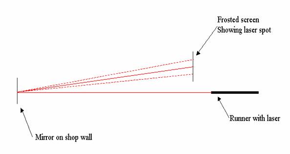
http://www.mailbag.com/users/sobering/PathFolding.png
Posted by: Paul Goodwin on January 29, 2004 at 14:03:22:
Posted by: P. Ashley on February 07, 2004 at 01:17:45:
Sails
Battens
Posted by: Doug Gaudet on January 30, 2004 at 14:56:38:
osted by: Paul Goodwin on February 06, 2004 at 08:31:19:
In Reply to: Battens-size? posted by Doug Gaudet on January 30, 2004 at 14:56:38:
Tell-Tale Streamers
Posted by: GeoffS on July 12, 2003 at 23:01:39:
Posted by: Ken Smith on November 19, 2003 at 00:00:55:
In Reply to: Far-forward tell-tales and mast rotation posted by GeoffS on July 12, 2003 at 23:01:39:
IMHO. From the back of the Gold fleet.
Posted by: Geoff S. on November 19, 2003 at 22:09:34:
Wow! What a "troll"! I can't wait to see this!
Seriously, thanks for the info.
Mast Rotation
Posted by: Paul Goodwin on November 20, 2003 at 08:44:10:
Rigging
Sources for Hardware
Posted by: Roger Livingston on February 06, 2002 at 07:34:56:
Posted by: Charlie on April 03, 2002 at 09:14:37:
In Reply to: Sarns posted by Roger Livingston on February 06, 2002 at 07:34:56:
Sarns new web address is www.sarnshardware.com -- Get ready for sticker price schock !
Rigging a Hull (Putting on hardware)
Posted by: Dave Rancilio on January 01, 2003 at 21:30:55:
Posted by: Jeff Soderholm on January 02, 2003 at 09:20:42:
In Reply to: Rigging hull posted by Dave Rancilio on January 01, 2003 at 21:30:55:
Posted by: Jeff Soderholm on January 02, 2003 at 22:29:13:
In Reply to: Re: Rigging hull posted by Davr Rancilio on January 02, 2003 at 14:49:24:
Posted by: Bob Rast DN1313 on January 02, 2003 at 15:12:04:
In Reply to: Re: Rigging hull posted by Davr Rancilio on January 02, 2003 at 14:49:24:
Springs on Front Chock
Posted by: John on June 21, 2004 at 08:49:13:
Where can I buy a spring that is used
on the DN ?
Thanks
Posted by: Geoff Sobering on June 25, 2004 at 12:11:58:
In Reply to: Front runner suspension spring posted by John on June 21, 2004 at 08:49:13:
If Sarns won't sell you one (sarnshardware.com), you might try McMaster-Carr (mcmaster.com).
Plank to Hull
Posted by: George on December 10, 2003 at 21:36:11:
DN 5250 is just about complete. A question remains:
Posted by: Bob rast DN1313 on December 10, 2003 at 22:23:03:
In Reply to: Plank bolt clearance holes. posted by George on December 10, 2003 at 21:36:11:
Bobstay
Posted by: dave on April 01, 2004 at 18:40:29:
Posted by: Geoff Sobering - US-5156 on April 02, 2004 at 11:28:17:
In Reply to: Bob Stay Cable Tension posted by dave on April 01, 2004 at 18:40:29:
Blocks (pulleys)
Posted by: Pete Ashley on November 24, 1999 at 02:13:47:
Posted by: Scott Crothers on December 12, 2003 at 15:39:25:
Posted by: Geoff Sobering on December 13, 2003 at 01:16:15:
In Reply to: Sheet Block Upgrade Ideas posted by Scott Crothers on December 12, 2003 at 15:39:25:
Posted by: Bob rast Dn1313 on December 13, 2003 at 08:34:46:
Posted by: John Jombock , DN1513 on December 13, 2003 at 15:40:37:
In Reply to: Sheet Block Upgrade Ideas posted by Scott Crothers on December 12, 2003 at 15:39:25:
John Jombock
136 Applewood Lane
Slippery Rock , PA 16057
724.794.4425 or jjblueskies@aol.com
Posted by: Jane Pegel on January 20, 2003 at 20:26:15:
Posted by: Gary on January 22, 2003 at 13:31:53:
In Reply to: Ratchet block safety warning posted by Jane Pegel on January 20, 2003 at 20:26:15:
Main Sheet
Posted by: Geoff Sobering on October 24, 2002 at 08:57:08:
Posted by: Paul Goodwin on October 30, 2002 at 15:49:39:
In Reply to: Re: Mainsheet suggestions? posted by Geoff Sobering on October 30, 2002 at 14:02:09:
Posted by: Paul Goodwin on October 31, 2002 at 18:18:00:
In Reply to: Re: Mainsheet suggestions? posted by Geoff Sobering on October 30, 2002 at 14:02:09:
As far as the tying the knots, I can tell you how to get started.
Posted by: Paul Goodwin on November 04, 2002 at 08:08:42:
In Reply to: Re: Mainsheet suggestions? posted by Paul Goodwin on October 30, 2002 at 15:49:39:
Posted by: Geoff Sobering on November 06, 2002 at 00:29:16:
In Reply to: Re: Mainsheet suggestions? posted by Geoff Sobering on November 05, 2002 at 13:44:00:
The latter is only available to those who are members of the Yahoo! "Iceboating" group.
Posted by: Pete Ashley on November 07, 2002 at 02:12:13:
In Reply to: Re: Mainsheet suggestions? posted by Geoff Sobering on November 06, 2002 at 00:29:16:
Posted by: Paul Goodwin on November 07, 2002 at 17:34:10:
In Reply to: Re: Mainsheet suggestions? posted by Pete Ashley on November 07, 2002 at 02:12:13:
Posted by: P. Ashley on November 09, 2002 at 23:57:00:
In Reply to: Re: Mainsheet suggestions? posted by Paul Goodwin on November 07, 2002 at 17:34:10:
Shrouds
Shroud lengths
Posted by: ken smith on December 15, 1999 at 08:09:03:
In Reply to: Re: Shroud measurement info posted by Frank M on December 11, 1999 at 12:33:03:
No one answered yet so here goes:
Posted by: Paul Goodwin on December 17, 1999 at 11:20:27:
In Reply to: Re: Shroud adjusters posted by ken smith on December 15, 1999 at 08:09:03:
Head Stay
Posted by: Jeff Brown on December 16, 2002 at 10:28:47:
Posted by: Ken Smith on December 16, 2002 at 19:07:34:
In Reply to: DN Extreme Rake stay lengths posted by Jeff Brown on December 16, 2002 at 10:28:47:
Posted by: Paul Goodwin on December 19, 2002 at 12:26:07:
In Reply to: Re: DN Extreme Rake stay lengths posted by Ken Smith on December 16, 2002 at 19:07:34:
Head stay length by other measures
Posted by: Jeff Soderholm on November 11, 2002 at 11:26:11:
In Reply to: Forestay length posted by Patrick Zachary on November 11, 2002 at 07:39:17:
Posted by: Geoff Sobering on November 11, 2002 at 19:49:53:
In Reply to: Re: Forestay length posted by Jeff Soderholm on November 11, 2002 at 11:26:11:
There are a couple of other ways to measure and compare mast rake:
Posted by: Patrick Zachary on November 12, 2002 at 16:58:20:
In Reply to: Re: Forestay length posted by Geoff Sobering on November 11, 2002 at 19:49:53:
Thanks Geoff & Jeff - I also got a personal reply from Jane Pegal suggesting:
Posted by: Paul Goodwin on December 19, 2002 at 12:19:12:
In Reply to: Re: Forestay length posted by Patrick Zachary on November 12, 2002 at 16:58:20:
Forestay hardware for mast rotation
Posted by: Ken Smith on December 30, 2002 at 19:30:45:
Or you can kick the boom over to the right side and not change anything.
Posted by: RBR on December 31, 2002 at 05:22:34:
by Ron Sherry – US 44 – December 1998
Posted by: Paul Goodwin on December 31, 2002 at 12:30:00:
In Reply to: Mast rotation hardware posted by Ken Smith on December 30, 2002 at 19:30:45:
Problems and solutions
Steering
Posted by: Doug Gaudet on January 18, 2000 at 08:13:53:
Posted by: Ken Smith on January 19, 2000 at 01:42:22:
Posted by: Bob Dill on January 19, 2000 at 09:42:57:
Posted by: Doug Gaudet on February 09, 2000 at 08:44:48:
How Tight to tighten runner bolts?
Posted by: Andre Baby on November 20, 2003 at 15:31:38:
Carrying boats around
Posted by: George on December 21, 2000 at 10:05:53:
In Reply to: Plans for roof rack posted by Jeff Smith on December 19, 2000 at 06:49:47:
What to take on the ice
Working on runners
Posted by: Paul Goodwin on March 02, 2004 at 09:33:47:
Other Iceboats
Optimist DN
Posted by: Ken Smith on May 30, 2002 at 08:32:34:
http://www.icesailing.org/junior/index.html
http://www.icesailing.org/index2.shtml
Ice Optimist class approved rules and
drawings
Sailplan and classrules (PDF)
Original ideas on the cheap
Saving epoxy rollers
Posted by: George on February 20, 2003 at 14:55:41:
Original Design Ideas
Posted by: Rick Keevil on March 31, 2003 at 20:53:51:
Posted by: Ken Smith on April 01, 2003 at 08:18:33:
In Reply to: NEW TOPIC: Albacore Sail etc. posted by Rick Keevil on March 31, 2003 at 20:53:51:
Posted by: Ken Smith on December 15, 2003 at 10:37:16:
Posted by: Wolfgang on December 15, 2003 at 17:16:33:
Posted by: kendnsmith@yahoo.com on December 19, 2003 at 07:16:34:
In Reply to: re: forward rake masts posted by Wolfgang on December 15, 2003 at 17:16:33:
Posted by: wayne matheson on December 19, 2003 at 18:57:20:
Skeeters
Posted by: Jordan Glaser on February 10, 2004 at 08:00:39:
Posted by: Paul Goodwin on February 11, 2004 at 08:39:24:
Actually, I
think you've got the rig tuning steps backward, at
least by my way of thinking.
Posted by: Jordan Glaser on February 11, 2004 at 20:50:34:
In Reply to: Re: DN bottoming out affect pointing? posted by dave on February 11, 2004 at 16:13:10:
Posted by: Paul Goodwin on February 12, 2004 at 08:09:46:
Asking a
DN'er questions on how to set up a Skeeter - I'm putting
this one on the calender!!!!!
Sorry I'm not more help, I should be asking you these questions!
Posted by: Jordan Glaser on February 12, 2004 at 21:13:46:
Two person boats
Posted by: Randy Beaton on February 16, 2000 at 12:43:32:
See also Jane Pegel's note in one of the sections below on boat design.
Posted by: Jeff Soderholm on February 16, 2000 at 22:14:07:
Posted by: mike derusha on March 21, 2000 at 18:39:44:
Colorful entertainment and writing
Posted by: Will on White Bear Lake on March 06, 2002 at 00:20:13:
In Reply to: Re: helmets posted by Roger Duffy on March 03, 2002 at 12:02:24:
All help appreciated. I must redeem myself to the ICE GODS of LAKE MINNETONKA!
2182
Posted by: Will on White Bear Lake on January 19, 2004 at 17:38:40:
Based on observation anyway. In our area (and I am talking about Recreational sailing NOT RACING) it seems that there are far more Nites that crash than DNs and yet we seem to have roughly equal numbers of both types of boats on the ice. It also seems, in general, the Nite pilots get far more serious injuries. Assuming this to be true...why?
I believe it has to do with the PERCEPTION of safety vs. the REALITY. This was brought home to me by an article entitled "Big and Bad" in the January 12, 2004 New Yorker. The artilce clearly illustrates why an SUV is much more likely to kill or cripple the driver and occupants (as well as those they clobber) than a good minivan or small agile car. In addition to being basically a crappy rigid pick-up frame covered with soft round corners, more seats, and cup holders, and the unarguable fact that the SUVs roll more and handle and brake poorly, they propose that MAIN REASON that SUV drivers and passengers are statistically 4X as likely to die at the wheel (238 fatalities/million vehicles on the road vs. 60 with a Toyota Avalon) or 67 for a Chrysler minivan) is that SUV'S FEEL SAFER THAN THEY ARE (all that chrome and rubber in front of you, 4WD, sound insulation, high seating position), while small cars FEEL MORE DANGEROUS THAN THEY ARE (engineered crumple-zones, MacPherson struts, real discs, low seating height, true road feel). This perception affects driving skills greatly, with the former lulling you into complacency, the latter more likely to cause you to pay attention.
When I read this I realized that piloting a DN generally tends to be a hair-raising experience requiring supurb attention to detail, particularly in super high wind or bad ice. The perceived speed is much greater than the actual speed virtually all the time. You watch for bumps, cracks and drifts! All this makes for an attentive and careful sailor! Death (from multiple sources) FEELS imminent most of the time!
Nites, on the other hand (while being intrinsically as safe, if not safer boats) are by comparison too comfortable, too warm and basically too secure feeling. As a result, the pilot has far less "road feel" and tends to increase the speed and course accordingly, just add some tinted windows and cup-holders for the full effect. One time I really did see a Nite guy on the cell phone (I'm serious!) as he went by. Yipes!
I plan to spend lots of time in both of these wonderful craft this winter (and many more winters to come, God willing) but I just hope I can always find and hold that edge without going over it. Let's all stay awake out there, whatever we ride!
WWBL
P.S. That SUV that busted up one of our WBL DNs Saturday was clipping right along when they hit. I would imagine some of the above SUV material applies to why they may not have seen the boat coming, and why they couldn't avoid the collision. We don't know what the DN guy was thinking about but it was more likely to be dodging drifts, not speeding hulks of steel.
Night Sailing
Posted by: Tim Polaski on March 12, 2003 at 13:51:05:
Posted by: Will on White Bear Lake on March 13, 2003 at 00:45:26:
In Reply to: Ice Boating at Night!!!!!!!!!!!! posted by Tim Polaski on March 12, 2003 at 13:51:05:
Posted by: Ken Smith on March 13, 2003 at 11:07:00:
In Reply to: Ice Boating at Night!!!!!!!!!!!! posted by Tim Polaski on March 12, 2003 at 13:51:05:
Posted by: Deb Whitehorse on March 13, 2003 at 12:22:02:
In Reply to: Ice Boating at Night!!!!!!!!!!!! posted by Tim Polaski on March 12, 2003 at 13:51:05:
Posted by: tdixon on March 15, 2003 at 08:33:40:
In Reply to: Ice Boating at Night!!!!!!!!!!!! posted by Tim Polaski on March 12, 2003 at 13:51:05:
Posted by: Paul Goodwin on March 26, 2003 at 09:41:00:
In Reply to: Ice Boating at Night!!!!!!!!!!!! posted by Tim Polaski on March 12, 2003 at 13:51:05:
You know you’re a DN’er when …
Posted by: Geoff Sobering on October 03, 2003 at 09:14:57:
How many different completions to the
phrase:
"You know you are a DN sailor when..."
I'm sure there are much better versions out there, but for example:
Posted by: brian on July 30, 2004 at 16:02:56:
Posted by: Geoff Sobering - US-5156 on April 02, 2004 at 00:15:39:
Posted by: Jeff Brown on October 17, 2003 at 18:54:17:
..You get nervous anytime you hear of the next giant iceberg calving-off in Antarctica.
Posted by: Scott Crothers on October 14, 2003 at 16:29:24:
You are happy that darkness falls at 6 P.M. rather than 9...
Hearing the furnace kick on gives you goosebumps...
Your wife encourages you to travel 1200 miles to look at a newer boat...
You shop for cold weather clothes in July...
A VW Beetle with a roof rack looks perfectly normal to you...
Posted by: Ken Smith on October 14, 2003 at 08:13:17:
You know you are a DN sailor when . . .
. . your car gets more hours every sailing weekend than your boat.
. . your car is overloaded when all your runners are loaded.
. . you think a weekend of freezing rain with a little wind and some smooth ice is a GREAT weekend.
. . having a great peel-off with your friends won't upset your wife.
. . leaving for a weekend of great peel-offs with your friends will upset your wife.
. . you think the only other season is ice season.
. . long underwear, fleece suit, wind pants, spandex top is cool sporty clothing.
. . you prefer track shoes for a winter sport.
. . you think bear claws are neither a doughnut nor something a bear walks on.
. . you know "regatta in Detroit" really means "thin ice"
. . you know "regatta in Madison" really means "fog and no wind"
. . you know "Minnesota Resort" means "there's a bar in the hotel"
. . you know a Minnesota regatta is west of everything.
. . you know "regatta in the UP" means it is going to snow tomorrow.